94
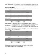
Setting the boiler address:
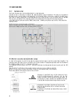
The managing boiler of the cascade system is connected to the AL-BUS connection on terminals 20-21
This connection also provides the power for the communication bus. The depending boilers are all parallel
connected to the managing boiler communication bus.
The bus power is provided by the managing boiler on terminals 20-21, switch S1 must be set in the OFF position
(all controls).
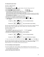
Figure: location of switch S1: red rectangle.
15.2.2 C
ASCADE
–
H
EATING ONLY
M
ANAGING BOILER
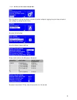
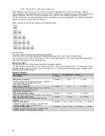
When a boiler is set as "Managing" (parameter 184: "Burner address"), the controller of this boiler will drive the
cascade. The CH mode of this managing boiler applies to all other boilers. It is only required to set the CH mode
on the managing boiler.
• The outdoor temperature sensor connected to the managing boiler will be the outdoor sensor for the cascade
operation
• The system sensor (T_System) connected to the managing boiler will be the control sensor for the cascade
supply temperature.
• The (modulating) thermostat connected to the managing boiler will be the CH heat demand input for the cascade
system.
Based on the system temperature (T_System) and the requested Cascade_Setpoint the managing boiler
calculates a required boiler setpoint, to achieve the requested Cascade_Setpoint.
The managing boiler provides the calculated setpoint to all dependent boilers. The modulating power of the
dependent boilers is PID controlled based on the calculated setpoint and dependent boiler supply temperature.
Cascade CH setpoint adaption
When the system temperature is not high enough the setpoint for all boilers will be adjusted.
The boiler setpoint will be increased when the system temperature drops below Cascade_Setpoint and decreased
when it rises above Cascade_Setpoint temperature.
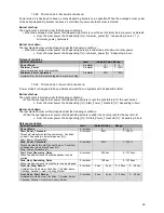
Dependent Boiler
The CH mode for the cascade is defined by the setting of the managing boiler. CH mode settings on dependents
are ignored. In case a boiler is set as "Dependent" (parameter 184: "Burner address") the setpoint is always
provided by the managing boiler.
The modulating power of the ALL boilers is PID controlled by the boiler itself by comparing the calculated setpoint
from the managing boiler and T_Supply. The managing boiler itself will be controlled in the cascade system as it
would as if it was a dependent boiler. Only the pumps and sensor inputs are used.
Boiler input Rates
A cascade system operates most effective and efficiently when all of the boilers in the system are the same size.
Address rules
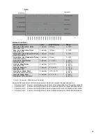
The cascade managing address (parameter 184) must be set to ‘Managing’ on the managing boiler.
The cascade depending addresses (parameter 184) must be set in a logical numbered order from 1: Dep. 1,
Dep. 2 etc. on the depending boilers.
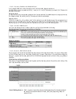
The total number of boilers in the cascade must be stored in parameter 147 on the managing boiler.
When the number of boilers is set to 4, the first three depending controls are expected to be available for the
cascade. In this case depending controls 1, 2 and 3 must be selected. When any of these 3 are not present
on the communication bus the managing control detects the loss of a depending control and generates the
warning: Comm. Lost with module.
J11
J8
OFF
ON
NOTICE
Summary of Contents for S-CBX 105
Page 2: ......
Page 40: ...40 9 10 Flue Terminal Positioning ...
Page 42: ...42 9 11 1 FIGURE 12 LINE G ...
Page 55: ...55 11 5 Ladder Logic Diagram ...
Page 56: ...56 11 6 Electrical schematics ...
Page 57: ...57 ...
Page 137: ......

