S-CB
+
Boiler Range Manual
118
19
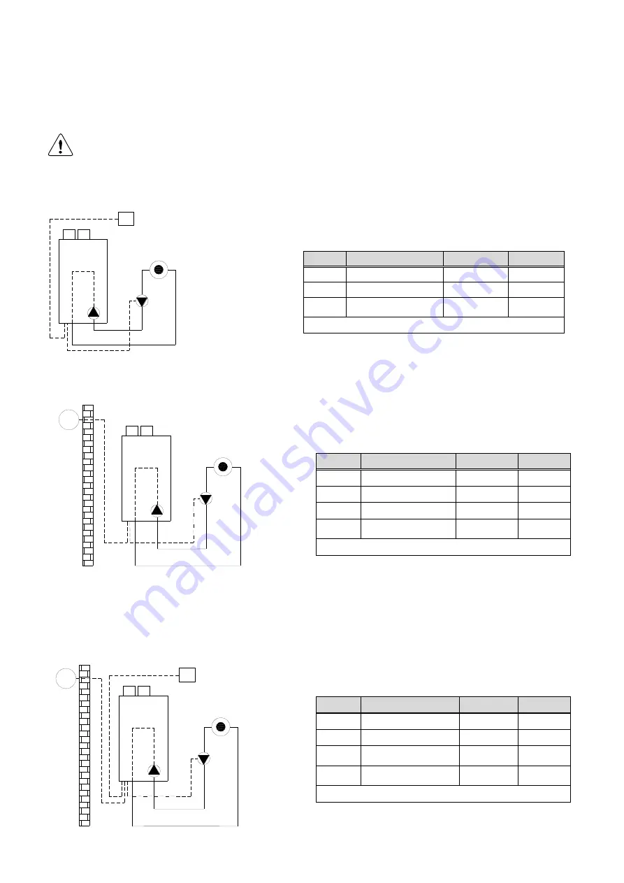
INSTALLATION EXAMPLES
The following schematics present several ways of mounting the heating installation:
All schematics are purely functional. Safety components must be added conform all applicable
standards and regulations.
System Type 1
Code 1
Name
Wire terminal
Order nr.
P1
built-in boiler pump
P3
optional heating pump
25-26-27
RT
modulating room unit
with timer
13-14
S04.016.355
No
parameter change needed
System Type 2
Code 2
Name
Wire terminal
Order nr.
P1
built-in boiler pump
P3
optional heating pump
25-26-27
place bridge
13-14
OS
outdoor temperature
sensor
1-2
E04.016.585
No
parameter change required
System Type 3
Code 3
Name
Wire terminal
Order nr.
P1
built-in boiler pump
P3
optional heating pump
25-26-27
RT
modulating room unit
with timer
13-14
S04.016.355
OS
outdoor temperature
sensor
1-2
E04.016.585
No
parameter change required
P3
P1
OS
RT
HEATING
ZONE
BOILER
P3
P1
OS
HEATING
ZONE
BOILER
RT
P3
P1
HEATING
ZONE
BOILER
Summary of Contents for S-CB+ Series
Page 2: ......
Page 3: ......
Page 22: ...S CB Boiler Range Manual 22 ...
Page 39: ...S CB Boiler Range Manual 39 9 4Electrical schematics ...
Page 124: ...S CB Boiler Range Manual 124 ...


