background image

11/07/00 

BOILER INSTALLATION INSTRUCTIONS FOR 
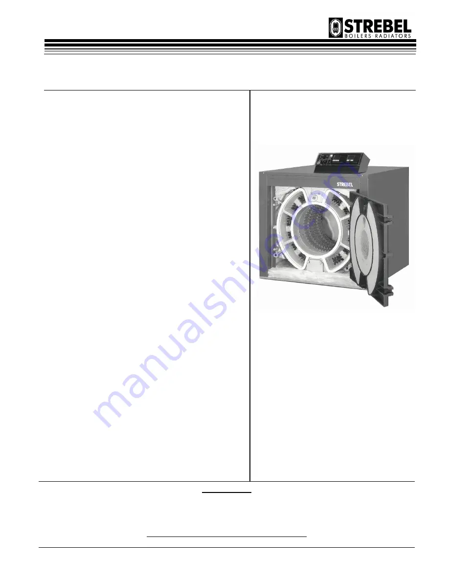


RU 1S / BRU 1 


RU 2S / BRU 2 


RU 3S 

ASSEMBLY INSTRUCTIONS 

General Instructions: 
 
The STREBEL RU boilers are special boilers for  oil or gas-fired 
(forced) burners. They can be fitted in hot-water heating 
installations. 
 
Operating Conditions: 
 
Hot-water Heating installations boiler  
Maximum Heat limit Temperature 110ºC / 130ºC 
Operating excess pressure normal working 4 bar 
Operating excess pressure multi-storey working 6 bar 
 
 
Please note all relevant instructions when assembling the boilers 
The Installation: The connecting and initial setting in operation 
should be carried out by a qualified heating specialist. 
The boiler base is to be constructed in accordance with our 
diagrams. 


IMPORTANT


THERE IS A STOP NUT BETWEEN THE BOILER DOOR AND THE DOOR SEAL  

(TO PROTECT THE DOOR SEAL DURING TRANSIT) 


THIS NUT MUST BE REMOVED ON SITE. 

Summary of Contents for BRU 1 Series

Page 1: ...mit Temperature 110ºC 130ºC Operating excess pressure normal working 4 bar Operating excess pressure multi storey working 6 bar Please note all relevant instructions when assembling the boilers The Installation The connecting and initial setting in operation should be carried out by a qualified heating specialist The boiler base is to be constructed in accordance with our diagrams IMPORTANT THERE ...

Page 2: ...Converting the burner door hinge Assembly of boiler connections Assembling the jackets and insulation BRU 1s Bicalor assembly completion BRU 1s Bicalor jacket insulation assembly Assembling the burner Gas connections Opening closing burner door Wiring details for control panel RU 2s Assembly section Fig 1 2 through to Fig 8 2 with corresponding notes RU 2s Jacket assembly RU 3s Assembly section Fi...

Page 3: ... running ratchet spanners 3 2 Stop pins 3 3 Pulling up nut with thrust bearing Items needed for construction flat chisel mallet brush small round smoothing file emery cloth cleanser e g petroleum inspection lamp spanner Note RU 2s Pulling up tools shown in Fig 4 2 and RU 3s tools in Fig 8 3 Advice on the use of the Pulling up tool 1 The pulling up flanges 1 at the rear section are screwed onto the...

Page 4: ...pple and borings should be apparent Before a nipple is inserted and a section fitted the nipple and the boring should be inspected Any damage e g to the face of the boring destroys the nipple seal and leads to leakage Attention Slight damage transport damage to the faces of the boiler nipple or to the nipple ports A can be corrected with a small smoothing file and emery cloth without affecting the...

Page 5: ...ASSEMBLY INSTRUCTIONS FOR Page 5 11 07 00 WALL CLEARANCE DIMENSIONS KEY A Boiler length min 200mm B Projection of burner min 100mm ASSEMBLY INSTRUCTIONS FOR RU 1s Assembly ...

Page 6: ...6 2 For RU 2s and Fig 7 3 For RU 3s Place boiler section in front of both inserted nipples Raise the boiler section onto the inserted nipples using a flat chisel under the section feet The inserted nipples must stand approx 1 to 2 mm higher than the boring of the section which is to be joined Using a crowbar raise the boiler section onto the inserted nipples until nipple and nipple ports mate and ...

Page 7: ...up If clearance is unequal insert a flat chisel in the narrower point and continue pulling up until clearance is equal again Avoid using excessive force Add on only one section at a time in each case Further sections not marked with white patch are added accordingly 7 Push tie bars 9 through the lugs on the ready a s s e m b l e d boiler block Slide a flat washer 10 and 2 disc springs 11 with conc...

Page 8: ...he flue gas temperature rises by a total of approx 40ºC NOTE RU 2s baffle details in Fig 8 2 The RU 3s range of boilers do NOT use flue gas baffles Alternatively they have ribbed intermediate sections denoted by the section legs painted in green Influence of water temperature A change of 10ºC in the water temperature produces a change in flue gas temperature of approx 5ºC 8ºC Boiler water and retu...

Page 9: ...MBLY INSTRUCTIONS FOR Page 9 11 07 00 NOTE Injector tube is not a requirement for the RU 2s and RU 3s boilers STREBEL RU 1s Injector tube in the STREBEL RU 1s return ASSEMBLY INSTRUCTIONS FOR RU 1s Assembly ...

Page 10: ...s not fixed into position it simply leans against the section wall To convert the burner door from right hand side to left hand side opening 1 Firmly shut the burner door 2 Undo and remove Hexagonal screws 18 on the lower left locking plate 17 3 Undo and remove stud bar 19 on front section 4 Undo and remove split pin 20 and crown nut 21 at the top right hand side 5 Undo hexagonal screws 18 on the ...

Page 11: ...6 12 Hexagonal nut M16 13 Flat washer 17 30 x 3 14 Rubber seal 152 115 x 5 15 Weld neck flange NW100 ND6 16 Hexagonal screw M16 x 60 17 Hexagonal screw M12 x 55 18 Blank flange 105 or pre welded flange 105 NW65 19 Flat washer 13 24 x 2 5 20 Hexagonal nut M12 21 2 x plugs NOTE RU 2s details shown in Fig 5 2 and RU 3s details in Fig 4 3 Fig 5 3 Cold Water Pressure Test The assembled boiler block sho...

Page 12: ...90x40x985 2 Flue gas housing insulation 50x180x2000 3 Rear jackets right and left hand 4 Protective metal sheet 5 Flue hood access door insulation 125x330x700 6 Flue hood access door jacket cover Boiler top insulation and front jackets 1 Cross bar at the top front 135x40x985 2 Insulation at the top rear 125x90x990 3 Insulation at the top front 125x135x990 4 Boiler top insulation 125x1100xL 5 Instr...

Page 13: ...n return valve 4 Circulating pump 5 plugs in the boiler return header 6 Levelling screws 7 2x x 150 Long immersion sensor pockets from the instrument panel are to be fitted into the boiler flow header If no circulating pipe has been supplied with the delivery then the piping must be constructed and made available In addition the non return valve is to be fitted as per the diagram The measurements ...

Page 14: ...top front 270x40x985 2 Insulation at the top rear 125x90x990 3 Boiler top insulation 125x1100xL 4 Rear under covering 5 Boiler front jacket right and left hand Fit the boiler top insulation to calorifier support through slits Calorifier side jacket Front and top jackets and instrument panel 1 Calorifier side jacket right and left hand 2 Calorifier top insulation 125x960xL 3 Calorifier top jacket 4...

Page 15: ...rgest possible diameter of the burner draught tube is limited by the boring 3 in the burner door 5 With regard to the choice of burner the burner head equipment stipulated by the manufacturer concerned should be used 6 Wrap burner draught tube with cerafelt fibre to insulate gap 4 7 Electrical connection should be made according to the electrical wiring in the instrument panel and IEE regulations ...

Page 16: ...ASSEMBLY INSTRUCTIONS FOR Page 16 11 07 00 ASSEMBLY INSTRUCTIONS FOR RU 1s Assembly ...

Page 17: ...ASSEMBLY INSTRUCTIONS FOR Page 17 11 07 00 ASSEMBLY INSTRUCTIONS FOR RU 1s Assembly ...

Page 18: ... carried out in accordance to IEE regulations Strebel RU boilers Single phase Installations 230V 1ph 59Hz The 1ph supply plus earth is taken to the relevant burner terminals and a separate 240V supply connected to the boiler instrument control panel Live L Neutral N and Earth E connections The control of the burner is then from the boiler instrument control panel via the supplied flying leads Stre...

Page 19: ...10 kg Flue gas collection housing 50 kg On completion of section assembly fit the 2 x plugs in the boiler return header Then fit the flow and return headers to the rear section and the blank flanges to the front section TICO Sound reducing framework A B RU 2s 8 1560 1200 RU 2s 9 1760 1400 RU 2s 10 1960 1600 RU 2s 11 2160 1800 RU 2s 12 2360 2000 RU 2s 13 2560 2200 RU 2s 14 2760 2400 Fig 3 2 Fig 2 2...

Page 20: ...s M12 x 35 2 Supporting washer 13 24 x 2 5 3 Blank flanges 105 4 Rubber seal 95 61 x 5 5 Hexagonal screw M16 x 35 6 Flat washer 17 30 x 3 7 Blank flange 105 8 Rubber seal 207 196 x5 9 Rubber seal 95 61 x5 10 Flat washer 17 30 x3 11 Hexagonal nut M16 12 Hexagonal nut M16 13 Flat washer 17 30 x 3 14 Rubber seal 152 115 x 5 15 Weld neck flange NW 150 ND6 16 Hexagonal screw M16 x 60 17 Hexagonal screw...

Page 21: ...ng the flue gas baffles 1 Open the boiler door 2 Insert flue gas baffles 16 inserting the number of pieces according to the table in the flue gas passes until they are touching as per diagram Fig 8 2 RU 2 Baffle arrangement RU 2s max kW oil kg h Nat gas m h 8 465 43 6 54 9 582 54 5 67 10 689 65 2 81 11 814 76 5 94 12 930 87 5 107 13 930 87 5 107 14 950 89 3 109 Type and no of sections Output and f...

Page 22: ...ASSEMBLY INSTRUCTIONS FOR Page 22 11 07 00 Follow the number order for jacket assembly completion ASSEMBLY INSTRUCTIONS FOR RU 2S BRU 2S RU 2s Assembly ...

Page 23: ...ASSEMBLY INSTRUCTIONS FOR Page 23 11 07 00 ASSEMBLY INSTRUCTIONS FOR RU 2S BRU 2S RU 2s Assembly ...

Page 24: ...h burner door 400 kg Front section without burner door 273 kg Burner door 127 kg Flue gas collection housing 65 kg Fit the 2x plugs in the boiler return header ASSEMBLY INSTRUCTIONS FOR ASSEMBLY INSTRUCTIONS FOR RU 3s Assembly TICO Sound reducing framework A B RU 3s 10 1910 1650 RU 3s 11 2110 1850 RU 3s 12 2310 2050 RU 3s 13 2510 2250 RU 3s 14 2710 2450 Fig 3 3 Fig 2 3 Fig 1 3 A B RU 3s 10 2510 15...

Page 25: ...ng bolts 9 Flange bolts 10 Blank flange and joint gasket 11 Blank flange and joint gasket 12 Slotted hinge bracket Fig 5 3 12 Small sound absorbing inserts 13 Cleaning covers 14 Large section of sound absorber 15 Flue gas collector hood 16 Flow 17 Return 18 Thermostat sensor pockets Continue to pressure test as per RU 1s instructions ASSEMBLY INSTRUCTIONS FOR Fig 4 3 Fig 5 3 ASSEMBLY INSTRUCTIONS ...

Page 26: ...d no of sections Output and fuel consumption Fig 6 3 Pulling up kit Fig 8 3 Key 1 Pulling up flange at the top rear section 2 Pulling up flange at the bottom rear section 3 Nipple flange 4 Pulling up flange for intermediate setions 5 Pulling up flange for front section 6 1 Basic bar 6 2 Extension bar 6 3 End piece bar 7 1 Free running ratchet spanner 7 2 Stop pins 7 3 Starting nut with thrust bear...

Page 27: ...ASSEMBLY INSTRUCTIONS FOR Page 27 11 07 00 ASSEMBLY INSTRUCTIONS FOR RU 3S Follow the number order for jacket assembly completion ASSEMBLY INSTRUCTIONS FOR RU 3s Assembly ...

Page 28: ...ASSEMBLY INSTRUCTIONS FOR Page 28 11 07 00 ASSEMBLY INSTRUCTIONS FOR RU 3S ASSEMBLY INSTRUCTIONS FOR RU 3s Assembly ...

Page 29: ...ASSEMBLY INSTRUCTIONS FOR Page 29 11 07 00 ...

Page 30: ...RS E O E STREBEL LTD 1F Albany Park Industrial Estate Frimley Road Camberley Surrey GU16 7PB Telephone 01276 685422 Fax 01276 685405 E mail address info strebel co uk Website www strebel co uk THE COMPANY RESERVES THE RIGHT TO CHANGE SPECIFICATIONS AND DIMENSIONS WITHOUT NOTICE ...

Reviews: