manualshive.com logo in svg
background image

Technical Data Manual

for use by engineers and heating contractors

5443 113  v1.9   05/2013 
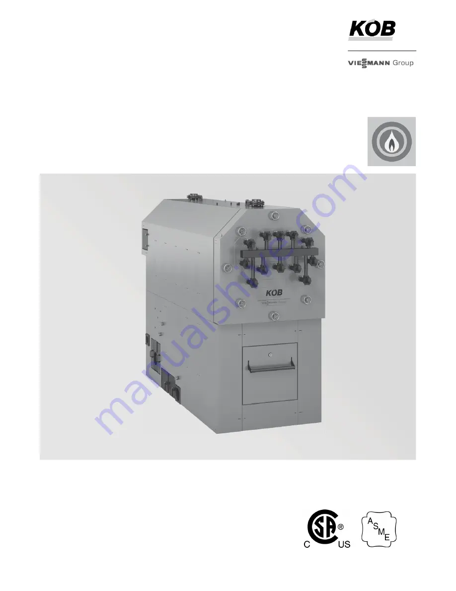
 

Pyrotec

r

Wood-fired Boiler
KPT 390 to KPT 1250 Series

Pyrotec with an attached external grate and a moving 
annealing grate to achieve optimal combustion results. 
A feed auger continuously moves the wood fuel onto 
the burner trough where gasification takes place.
The combustible gases blend with precisely controlled 
secondary air, resulting in a complete combustion and
the thermal energy is released into the boiler’s triple-pass 
heat exchanger.
Max. output: 390 to 1250 kW (1331  to 4266 MBH)
Min.  output:   98 to   370 kW (334  to 1263 MBH)

Product may not be exactly as shown

Содержание KOB Pyrotec KPT Series

Страница 1: ...timal combustion results A feed auger continuously moves the wood fuel onto the burner trough where gasification takes place The combustible gases blend with precisely controlled secondary air resulting in a complete combustion and the thermal energy is released into the boiler s triple pass heat exchanger Max output 390 to 1250 kW 1331 to 4266 MBH Min output 98 to 370 kW 334 to 1263 MBH Product m...

Страница 2: ...ting systems Under certain conditions open loop systems may also be considered Contact Viessmann for details Specifications Fully automatic underfeed combustion wood fired boiler 5 models from 1330 to 4268 MBH For wood fuels with max water content of 50 Efficiency 85 Available for 30 or 60 psi max operating pressure Benefits at a glance High efficiency with advanced combustion technology triple pa...

Страница 3: ...eat is transferred to the water in the horizontal tube heat exchanger The boiler is well insulated and highly accessible through the boiler door on the front A pneumatic cleaning system optional can be installed at the insulated boiler door The flue gas blower has been specially designed for wood burning boilers and quiet operation The spring suspended motor has a solid heat resistant design with ...

Страница 4: ... attached A special crane provided by the customer on site is required to lift the fire box and the pressure vessel Recommended minimum clearances to walls for installation and maintenance work must be observed An anti vibration boiler support should be provided if anti vibration measures are required IMPORTANT A Lifting lugs screw in before lifting B Lifting lugs pressure vessel WARNING Follow in...

Страница 5: ...oor is mounted to the tube heat exchanger Fire box door is mounted to the fire box Flue gas collector is attached to the tube heat exchanger Pneumatic cleaning system optional is attached to the tube heat exchanger door Components that are not attached or installed to the boiler at time of delivery scope of the contractor The pressure vessel is not mounted to the fire box Brickwork to connect the ...

Страница 6: ...ated and treated wood in the form of shavings from processing machinery and chips from choppers Used wood This is untreated wood that has been used prior to its energetic utilization e g pallets It is reduced in size by shredders for thermal utilization The metal parts have to be removed by magnetic separators If different fuels are used Viessmann will not assume any liability for the functioning ...

Страница 7: ...cription a S130 8 1 W10 to W20 C1 Sawdust untreated planing shop b1 S200 12 5 W20 to W35 C1 Sawdust untreated sawmill c2 S250 15 6 W35 to W50 C1 Sawdust untreated sawmill Wood chips Fuel code Bulk Density kg m lb ft Water content Fuel Size Description b2 S200 12 5 W20 C7 Forest wood chips soft untreated c1 S250 15 6 W20 to W35 C7 Forest wood chips soft untreated d1 S300 18 7 W20 to W35 C7 Forest w...

Страница 8: ... or plastics Substance Limit Comparative value untreated forest wood Chlorine Cl max 300 ppm 300 mg kg 10 ppm 10 mg kg Sulphur S max 1000 ppm 1000 mg kg 120 ppm 120 mg kg Total Cl S max 1000 ppm 1000 mg kg 130 ppm 130 mg kg Ash content total max 0 25 oz lb 15 0 g kg 0 08 oz lb 5 0 g kg Alkali oxides in the ash K2O and Na2O max 0 016 oz lb 1 0 g kg 0 006 oz lb 0 35 g kg Sintering point of the ash m...

Страница 9: ...t in case of a power failure the boiler will be reliably cooled by the thermal run off safety valve Power Failure Provision For installations in Canada The boiler venting system must be tested and listed by a Nationally Recognized Testing Lab such as ULC CSA for solid fuel burning appliances The PYROTEC Grate Firing System is output controlled within a range from 30 100 of the rated boiler output ...

Страница 10: ...terials may be stored in the heating room The heating boiler may only be set up on a fire and temperature resistant floor The load bearing capacity of the heating room floor must be designed for the weight of the system plus filling with water and fuel The load bearing capacity of the floor in the area of the boiler bearing surface must be 512 lb ft 2500 kg m IMPORTANT Always follow the most up to...

Страница 11: ...ock the flow of adequate fresh air to the boiler Never cover the combustion air opening Advise system operator ultimate owner accordingly Confined spaces When a furnace or boiler is enclosed in a space that has a volume less than 20 of that to be heated by the appliance the space shall a have a permanent opening or openings for natural air circulation with a minimum net free area of 1 5 in 1000 Bt...

Страница 12: ... 23 23 383 1450 457 5 42 5 602 2280 17 26 43 488 1850 597 4 55 5 774 2830 10 5 26 515 1950 805 2 74 8 1070 4050 18 45 660 2500 979 6 91 0 1367 5210 63 221 240 800 63 221 240 800 113 7 8 30 or 60 2 or 4 250 120 149 65 Weight Weight of fire box Weight of pressure vessel 30 psi Weight of pressure vessel 60 psi Weight of displacement rods Weight of flue gas blower Weight of in feed auger Total weight ...

Страница 13: ... 22 577 22 577 22 577 257 8 657 257 8 657 f in mm 47 1200 47 1200 47 1200 50 1275 50 1275 g in mm 94 2405 1143 8 2905 1177 8 2993 1125 8 2861 1341 8 3406 h in mm 42 1086 42 1086 543 8 1380 63 1612 63 1612 k in mm 315 8 803 315 8 803 315 8 803 365 8 929 365 8 929 l in mm 177 8 453 177 8 453 177 8 453 187 8 479 187 8 479 m in mm 81 2077 91 2331 981 8 2491 96 2444 1037 8 2639 n in mm 121 8 308 121 8 ...

Страница 14: ... Igniter optional G Cleaning cover trough H Cleaning cover external grate K Light barrier de ashing system L Boiler door M Pneumatic cleaning system N Combustion chamber door O Limit switch combustion chamber door P Primary air blower 2 Q Drive in feed grate R Temperature sensor in feed auger S Limit switch maintenance cover T Light barrier in feed auger U Extinguishing water connection V Boiler d...

Страница 15: ...periodic blasts of compressed air while the system is in regular operation During the cleaning process the individual sections are blasted clean one after another The ash on the heat exchanger tubes is detached by very short but strong blasts of air The particles detached are conducted by the flow of gas to the de duster where most are filtered out and collected The system is built into the boiler...

Страница 16: ...e duster is fully insulated and has three covers for cleaning The crude gas chamber is cleaned via the side cleaning cover The clean gas chamber is cleaned via the upper or back cleaning cover unused blower connection The ash box has a carriage and is connected to the de duster with quick action fasteners It can easily be pulled out for emptying The blower can be installed either on the side or th...

Страница 17: ...i or 60 psi KPT 1250 30 psi only Q 4 in or 6 in Boiler supply flange 3 R Supply sensor well sensor supplied S 4 in or 6 in Boiler return flange 3 T Return sensor well sensor supplied U Sensor wells for thermal safety flush valve Rb in sensor supplied 1 See section Piping and Installation of Safety Devices 2 Two PRVs must be installed on the KPT 1250 30 psi boiler One PRV must be installed and the ...

Страница 18: ...em return line Bypass line Boiler return line Blocked port Valve adjustment must be facing forward Adjustment Piping and Installation of Safety Devices Legend A Additional heat source B Storage tank as low loss header option A 5 sensors C Distributor heat consumer D Storage tank 1 E Storage tank 2 F Two storage tanks as low loss header option B 5 sensors 1 2 and 3 indicates system connections Mech...

Страница 19: ...model KPT Pressure relief valve Conbraco 1 Drain pipe PDP 2 30 psi 60 psi 30 psi 60 psi 390 1a in 1 in 1b in 1a in 530 1b in 1a in 2 in 1b in 720 2 in 1a in 2b in 1b in 950 2 in 1b in 2b in 2 in 1250 2 in 2 in 2b in 2 in Note To reliably prevent boiler corrosion caused by condensation of flue gases the boiler return flow temperature must not under any circumstances be below 150 F 65 C A Viessmann ...

Страница 20: ...the fire box Back flash safeguard The PYROTEC Grate Firing System is operated with continuous negative pressure and is equipped with a back flash prevention device This device prevents back flashes caused by flying embers or combustible gases that may ignite the fuel system Automatic in feed auger extinguishing system The supplied fire extinguishing system is necessary on the in feed auger This sy...

Страница 21: ...red a suitable safeguard against back burn Max overpressure allowed in fuel storage unit 500 Pa 2 00 wc Max negative pressure allowed in fuel storage unit 0 Pa 0 wc Fire Protection continued IMPORTANT IMPORTANT IMPORTANT Double rotary valve with pressure compensation system If due to special circumstances any mechanically produced negative pressures or extraordinarily high overpressures are expect...

Страница 22: ...Note The fire extinguishing system for the in feed auger is part of the boiler Line from the extinguishing water container to the b in valve as short as possible Valve thermostatic Danfoss AVTA 15 122 F 194 F 50 90 C position 3 equals approximately 176 F 80 C The lines must be executed as hard piping in metal b in It must not be possible to shut off the cold water inlet without the aid of tools Be...

Страница 23: ...e fuel air mixture by a lambda sensor Pressure regulation of the fire box with constant negative pressure guaranteed Fire box temperature limitation with the required variation of the air index to protect the fire resistant lining Upholding the return temperature with the boiler mixing valve provides for a long service life of the boiler Electrical Vitocontrol Safety functions for Excess temperatu...

Страница 24: ...t limitation 0 0 5 V OFF 0 6 3 V Maintain embers 3 1 10 V 30 to 100 output operation Note Installation of Output signals 0 10 V is possible according to irrespective of any additional control system components to be used Operational Message Function System status Operating Load indication from operation of the boiler pump to higher level control Supplied with Floating output operational message Ex...

Страница 25: ...Boiler supply temperature sensor 23 B20 1 107B20 1 Boiler return temperature sensor 24 B27 73B27 Fire box temperature sensor not shown Light barriers 25 B1G 1 61B1G 1 Light barrier embers Transmitter not shown 26 B1G 2 61B1G 2 Light barrier embers Receiver not shown 27 B2 1 61B2 1 Light barrier in feed auger Transmitter 28 B2 2 61B2 2 Light barrier in feed auger Receiver 29 B14 1 61B14 1 Light bar...

Страница 26: ...26 5443 113 v1 9 Pyrotec Technical Data Electrical Number Designation Device tag Description A M9 9 M9 Motor for rotary valve Rotary Valve Fuel Transport and Extraction Systems ...

Страница 27: ... 45 M10 2 8M10 2 Slide valve T30 46 B02 107B02 In feed auger temperature sensor Note For details on designation see field wiring diagram Pipe trough conveyor auger Number Designation Device tag Description 47 M4 1 5M4 1 Motor for pipe trough conveyor auger 48 S4 1 68S4 1 Limit switch for maintenance lid 49 B4 1 1 61B4 1 1 Light barrier conveyor auger Transmitter 50 B4 1 2 61B4 1 2 Light barrier co...

Страница 28: ... switch for maintenance lid 53 S32 2 12S32 2 Limit switch for silo door not shown Note For details on designation see field wiring diagram Number Designation Device tag Description 54 M32 12M32 Motor for spring extraction system 55 S32 1 12S32 1 Limit switch for maintenance lid 56 S32 2 12S32 2 Limit switch for silo door not shown Note For details on designation see field wiring diagram Spring ext...

Страница 29: ...em Number Designation Device tag Description 57 M32 12M32 Motor for extraction auger 58 M33 12M33 Motor for agitator 59 B32 12B32 Light barrier for extraction auger 60 S32 1 12S32 1 Safety switch for maintenance lid 61 S32 2 12S32 2 Safety switch for silo door not shown Note For details on designation see field wiring diagram ...

Страница 30: ...tion Device tag Description 62 M2 4M2 Motor for walking floor auger 63 S3 68S3 Safety switch for maintenance lid 64 S3 1 68S3 1 Safety switch for auger cover 65 B3 1 61B3 1 Light barrier walking floor auger Transmitter 66 B3 2 61B3 2 Light barrier walking floor auger Receiver 67 B6 1 1 61B6 1 1 Light barrier silo distribution top Transmitter 68 B6 1 2 61B6 1 2 Light barrier silo distribution top R...

Страница 31: ...mperature sensor not shown Note For details on designation see field wiring diagram Silo Lid Number Designation Device tag Description 76 Y6 3 22Y6 3 Solenoid valve silo lid open 77 Y6 4 22Y6 4 Solenoid valve silo lid close 78 S6 1 22S6 1 Key operated switch for silo lid 79 M901 24M901 Vibration motor 1 80 M902 24M902 Vibration motor 2 81 M903 24M903 Vibration motor 3 82 S901 24S901 Key operated s...

Страница 32: ... the initial operation the material to be burned for the initial operation has to be at least air dry For the first three hours the heating up process should be carried out at low output To ensure that the silo extraction system is functioning properly only place a minimal amount of fuel in the silo in case there is a problem This enables the extraction system to be cleaned out quickly and the pro...

Отзывы: