Electrical System
39/47
Z001138-1_2013-02-01
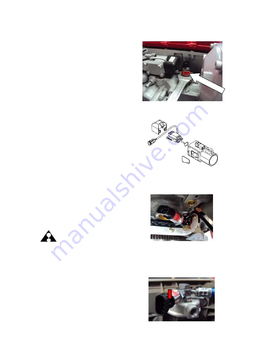
06.10.04.04 MAP – Manifold Absolut Pressure Sensor, B04
1. Pull off plug by turning counterclockwise.
2. Loosen sensor (SW27). Remove sensor.
Assembly is done in reverse order off
disassembly.
For replacing the sensor use
LOCTITE 243.
06.10.04.05 RPos - Sensor for rack position, B01
1. Remove retaining clip, remove plug
housing .
2. Disassemble rack control solenoid, refer
to 03.08.01.
3. Loosen 2 hex.sock.hd.cap-screws with
hexagon socket (SW3), remove sensor.
Assembly is done according to assembly
of rack control solenoid, refer to 03.08.
06.10.04.06 LPS - Lubricant pressure sensor, B05
1. Remove plug housing.
2. Unscrew lubricant pressure sensor SW 22
(from mount
ATTENTION:
Avoid spilling of engine oil.
Collect lubricant in a
suitable container.
3. Mount sensor with new cupper seal and
tighten to 28 Nm +/-2.
Use
LOCTITE 243
06.10.04.07 FSP – Fuel Supply Pressure Sensor B10
1. Remove plug housing.
2. Unscrew Fuel Supply Pressure sensor
(SW 22)
3. Mount sensor by use of
LOCTITE 243
.
Summary of Contents for Marine Engine 2012 Series
Page 35: ...General 35 65 Z001138 1_2013 02 01 Trouble Indication ...
Page 36: ...General Preliminary Service Manual MARINE 2012 Z001138 1_2013 02 01 36 65 ...
Page 51: ...General 51 65 Z001138 1_2013 02 01 G Notes on safety ...
Page 69: ...Engine Z001138 1_2013 02 01 4 87 Kapitel MOUNT BRACKET COVER T BELT GASKET SET ...
Page 154: ...Fuel System Z001138 1_2013 02 01 2 51 ...
Page 159: ...Fuel System 7 51 Z001138 1_2013 02 01 03 00 03 Unit injector ...
Page 190: ...Fuel System Z001138 1_2013 02 01 38 51 Schema Injection Timing Device ITD ...
Page 211: ...Cooling System 5 21 Z001138 1_2013 02 01 ...
Page 231: ...Electrical System Z001138 1_2013 02 01 4 47 ...
Page 235: ...Electrical System Z001138 1_2013 02 01 8 47 ...
Page 236: ...Electrical System 9 47 Z001138 1_2013 02 01 ...
Page 238: ...Electrical System 11 47 Z001138 1_2013 02 01 ...


