General
41/65
Z001138-1_2013-02-01
Final Ten Hours of Break-in
During the final ten hours of break-in, the engine may run at full speed for five to ten
minutes. Operate engine to with specified temperature, at moderate engine speed
increase to cool down engine, occasionally reduce the engine speed and load.
NOTE: DURING THE BREAK-IN PERIOD, THE ENGINE MUST NOT BE OPERATED
AT CONSTANT
RPM FOR LONGER PERIODS.
During break-in period, be particularly observant of the following:
A. Check motor oil level daily. Always maintain oil level in the desired range between the
"MIN" and "MAX" marks on dipstick. When refilling motor oil, refer to information "
Motor
Oil"
(B 2).
B. Check oil pressure control lamp. Check the oil level in the engine housing by means of
dipstick. If necessary, add oil (
DO NOT
OVERFILL)
. In case that the oil pressure control
lamp would illuminated check for correct oil level, have the engine checked by your
STEYR Service dealer as to malfunction of signal or oil pump.
NOTE:
During normal operation of engine, oil pressure will rise as RPM increases and fall
as RPM decreases. In general, oil pressure will be higher with cold motor oil and specific
RPM than with hot motor oil.
C. Check engine temperature indication. Normal operation between 80° - 95°. In case of
audible alarm, check coolant level in expansion tank (only at cold engine before starting).
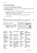
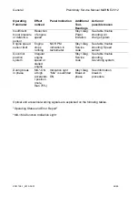
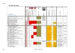
D. Deviations from normal operating conditions will be indicated by warning lights and
audible alarm. As to exact meanings see 06.07.02 & 06.07.05.
ATTENTION: In case of non observance of break-in instructions, warranty will
expire.
Engine to be filled with recommended oil quality only. See chapter "Engine
Lubrication"
Summary of Contents for Marine Engine 2012 Series
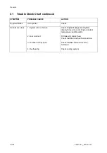
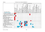
Page 35: ...General 35 65 Z001138 1_2013 02 01 Trouble Indication ...
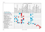
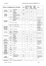
Page 36: ...General Preliminary Service Manual MARINE 2012 Z001138 1_2013 02 01 36 65 ...
Page 51: ...General 51 65 Z001138 1_2013 02 01 G Notes on safety ...
Page 69: ...Engine Z001138 1_2013 02 01 4 87 Kapitel MOUNT BRACKET COVER T BELT GASKET SET ...
Page 154: ...Fuel System Z001138 1_2013 02 01 2 51 ...
Page 159: ...Fuel System 7 51 Z001138 1_2013 02 01 03 00 03 Unit injector ...
Page 190: ...Fuel System Z001138 1_2013 02 01 38 51 Schema Injection Timing Device ITD ...
Page 211: ...Cooling System 5 21 Z001138 1_2013 02 01 ...
Page 231: ...Electrical System Z001138 1_2013 02 01 4 47 ...
Page 235: ...Electrical System Z001138 1_2013 02 01 8 47 ...
Page 236: ...Electrical System 9 47 Z001138 1_2013 02 01 ...
Page 238: ...Electrical System 11 47 Z001138 1_2013 02 01 ...

