General
Preliminary
Service Manual MARINE 2012
Z001138-1_2013-02-01
38/65
Starting the Engine
Starting procedure for the
STEYR MOTORS engine
is the same for both cold and warm engines. The
engine control unit
automatically regulates the fuel supply and the preheating period
, for any given
temperature. Therefore, the throttle lever should remain in neutral position.
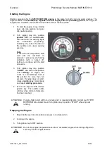
1. To start the engine, move throttle
lever into idle position and gear
into neutral position.
2. Turn ignition key into position
ignition “ON”
. An audible alarm
will sound and the warning lights
are illuminated (temporary),
indicating the correct function of
the audible and visual warning
systems.
Note:
In case of a low temperature start
wait until the combined oil
pressure / glow plug pre-heating
indication light is turned off,
before you continue with the start
procedure.
3. Turn ignition key into position
“START”
and hold in this position
until
“starting”
of engine, but
under no circumstances hold in
this position for more than ten
seconds. If engine does not start,
release
ignition key
momentarily
and repeat
starting procedure
.
4. As soon as engine starts, release
ignition key. The audible alarm
will stop when normal oil pressure
has been reached.
If engine fails to start within one minute and / or repeated attempts, contact your STEYR
MOTORS Marine dealer. Never turn ignition key to position “START” when engine is
running.
Stopping the Engine
1. Move throttle lever into idle position and gear in neutral position.
2. Cool down the engine.
3. Turn ignition key to OFF position
Do not stop engine at speeds above idle or “accelerate” engine while turning off ignition.
This may result in engine failures.
Summary of Contents for Marine Engine 2012 Series
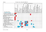
Page 35: ...General 35 65 Z001138 1_2013 02 01 Trouble Indication ...
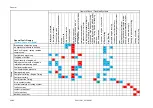
Page 36: ...General Preliminary Service Manual MARINE 2012 Z001138 1_2013 02 01 36 65 ...
Page 51: ...General 51 65 Z001138 1_2013 02 01 G Notes on safety ...
Page 69: ...Engine Z001138 1_2013 02 01 4 87 Kapitel MOUNT BRACKET COVER T BELT GASKET SET ...
Page 154: ...Fuel System Z001138 1_2013 02 01 2 51 ...
Page 159: ...Fuel System 7 51 Z001138 1_2013 02 01 03 00 03 Unit injector ...
Page 190: ...Fuel System Z001138 1_2013 02 01 38 51 Schema Injection Timing Device ITD ...
Page 211: ...Cooling System 5 21 Z001138 1_2013 02 01 ...
Page 231: ...Electrical System Z001138 1_2013 02 01 4 47 ...
Page 235: ...Electrical System Z001138 1_2013 02 01 8 47 ...
Page 236: ...Electrical System 9 47 Z001138 1_2013 02 01 ...
Page 238: ...Electrical System 11 47 Z001138 1_2013 02 01 ...

