Engine
Z001138-1_2013-02-01
64/87
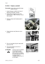
1. Lift engine with special tool No.
VR00130/0 and crane
(min. 3500 N).
2. Dismantle oil separator and crank case
ventilation hose
3. Remove oil filter and oil hose entirely
4. Remove intake manifold.
5. Disconnect oil pipe from coolant
distribution pipe and remove coolant
distribution pipe.
6. Disconnect oil hose on oil pump SW 10
NOTE:
Tightening torque of fitting on oil hose
9,5 Nm +/-1
.
7. Mount it on No. VR00102/0 and trestle
No. VR00101/0 by means of four
hexagon screws M8x30 SW13.
ATTENTION:
thread screwing depth
1,5xD
For mounting bracket
Summary of Contents for Marine Engine 2012 Series
Page 35: ...General 35 65 Z001138 1_2013 02 01 Trouble Indication ...
Page 36: ...General Preliminary Service Manual MARINE 2012 Z001138 1_2013 02 01 36 65 ...
Page 51: ...General 51 65 Z001138 1_2013 02 01 G Notes on safety ...
Page 69: ...Engine Z001138 1_2013 02 01 4 87 Kapitel MOUNT BRACKET COVER T BELT GASKET SET ...
Page 154: ...Fuel System Z001138 1_2013 02 01 2 51 ...
Page 159: ...Fuel System 7 51 Z001138 1_2013 02 01 03 00 03 Unit injector ...
Page 190: ...Fuel System Z001138 1_2013 02 01 38 51 Schema Injection Timing Device ITD ...
Page 211: ...Cooling System 5 21 Z001138 1_2013 02 01 ...
Page 231: ...Electrical System Z001138 1_2013 02 01 4 47 ...
Page 235: ...Electrical System Z001138 1_2013 02 01 8 47 ...
Page 236: ...Electrical System 9 47 Z001138 1_2013 02 01 ...
Page 238: ...Electrical System 11 47 Z001138 1_2013 02 01 ...


