


– 67 –
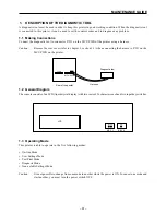
MAINTENANCE GUIDE
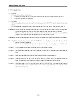
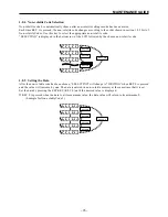
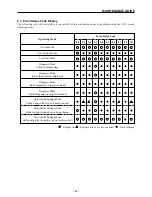
1.7.5
Diagnosis Code Selection
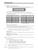
When diagnosis mode is entered, diagnosis code 30 is the first code displayed.
Each time KEY 1 is pressed, the diagnosis code changes according to the order shown in section 1.7.4 List of Diagnosis Codes.
D
G
3
0
KEY1 ON
KEY1 ON
KEY1 ON
KEY1 ON
KEY1 ON
KEY1 ON
KEY1 ON
KEY1 ON
KEY1 ON
KEY1 ON
KEY1 ON
KEY1 ON
D
G
0
2
D
G
0
7
D
G
0
8
D
G
8
0
D
G
9
0
D
G
9
1
D
G
0
0
D
G
0
0
D
G
0
0
D
G
9
5
D
G
9
4
D
G
9
3
D
G
9
2
KEY1 ON
KEY1 ON
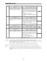
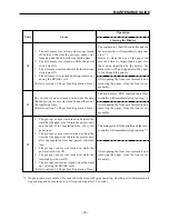
Caution:
When diagnosis code 02 (input test mode) is being executed, KEY 0 cannot be used to choose another
diagnosis code since it has another function under diagnosis code 02.
When a diagnosis code other than code 02 (input test mode) is being executed, another diagnosis code
can be chosen by pressing KEY 0.
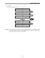
1.7.6
Input Test (Diagnosis Code 02 (“SENSOR CHECK”))
(1)
Function
Each time a sensor or switch is turned ON, the (two-digit, decimal number) number on the bottom right of the LCD
is increased by one.
This number allows you to verify that the switch and sensors are functioning properly.
(2)
Operation
After entering diagnosis mode and choosing diagnosis code 02 with KEY 1, press KEY 0 to begin the check to
determine whether the switch and sensors are operating correctly.
Press KEY 0 to stop the diagnosis and return to the initial display shown when diagnosis code 02 was chosen.
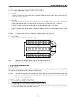
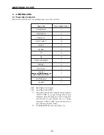
(3)
LCD Display
(4)
Verification
This code artificially turns on the switch and sensors, counts the number of switches and sensors that turned on and
displays this number in the bottom right corner.
The following switches and sensors are checked:
• Interlock Switch
• CRU Sensor
• Pre-regi. Sensor
• Exit Sensor
Warning:
Do not turn on the interlock switch and the LD switch (on the CRU sensor PWB) at the same time
while making a diagnosis with the front cover assembly open since the laser beam may be emitted.
If the two switches must be turned on at the same time, be sure to disconnect the connector (P/J171)
from the CRU sensor PWB or the connector (P/J12) from the MCU PWB.
Each time a switch or sensor is turned ON, the
(two-digit, decimal number) increases by one.
S
E
N
S
O
R
C
S
E
L
E
C
T
I
N
H
E
C
K
G
D
G
0
2
S
E
N
S
O
R
C
E
X
E
C
U
T
I
N
H
E
C
K
G
D
G
0
0
KEY0 ON
Summary of Contents for WinType 4000
Page 1: ...WinType 4000 TECHNICAL MANUAL SECOND EDITION LASER PRINTER ...
Page 4: ......
Page 6: ... 2 GENERAL SPECIFICATIONS ...
Page 14: ... 10 THEORY OF OPERATION ...
Page 26: ... 22 THEORY OF OPERATION Figure 2 9 Electrical ...
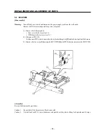
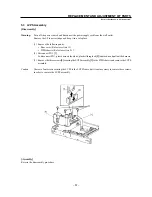
Page 28: ... 24 REPLACEMENT AND ADJUSTMENT OF PARTS ...
Page 62: ... 58 REPLACEMENT AND ADJUSTMENT OF PARTS ...
Page 64: ... 60 MAINTENANCE GUIDE ...
Page 114: ... 110 MAINTENANCE GUIDE ...
Page 116: ... 112 TROUBLESHOOTING ...
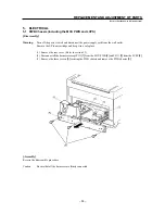
Page 176: ... 172 5 ELECTRICAL 5 1 Disassembly Drawing 1 2 3 4 14 4 14 2 14 1 14 3 13 12 11 6 5 7 8 9 10 ...
Page 179: ......