


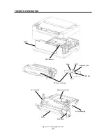


CHAPTER 3
REPLACEMENT AND ADJUSTMENTS OF PARTS
This chapter explains adjustment, disassembly and reassembly of the printer. The following precautions should be
noted during disassembly and reassembly:
1. Disconnect the printer from the wall outlet before servicing it.
2. Unless otherwise specified, the printer is assembled by reversing the disassembly procedure.
3. Do not operate the printer with any parts removed.
4. When you remove the EPX toner cartridge, be sure to keep the cartridge in its original box. If the box is not
available, cover the cartridge with a cloth or put it in a dark place to prevent light from affecting the drum inside
the cartridge.
3
1.
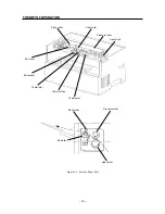
COVERS .............................................. 25
1.1
Front Cover .................................... 25
1.2
Top Cover ....................................... 26
1.3
Rear Cover ...................................... 27
1.4
Bottom Cover ................................. 28
1.5
Fan .................................................. 29
2.
FEEDER & DRIVE ............................... 30
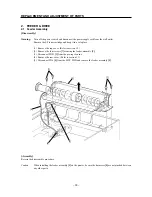
2.1
Feeder Assembly ........................... 30
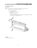
2.2
Feed Roller Assembly ................... 31
2.3
Feed Solenoid ................................ 32
2.4
Paper Set Lever .............................. 33
2.5
Retard Pad ...................................... 34
2.6
Pre-Regi. Sensor ............................ 35
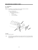
2.7
Drive Assembly .............................. 36
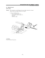
2.8
Main Motor ...................................... 37
3.
FUSER ................................................. 38
3.1
Fuser Assembly ............................. 38
3.2
Pressure Roller .............................. 39
3.3
Heater Rod ...................................... 40
3.4
Heat Roller ...................................... 42
3.5
Thermostat ..................................... 43
3.6
Thermal Fuse ................................. 44
3.7
Thermistor ...................................... 45
3.8
Exit Sensor ..................................... 46
4.
ROS...................................................... 47
4.1
ROS Assembly ............................... 47
4.2
SOS Sensor Assembly .................. 48
4.3
Laser Diode .................................... 49
4.4
Scanner Assembly ......................... 50
4.5
Mirror .............................................. 51
4.6
HVPS ............................................... 52
4.7
Front Cover Interlock Switch
Actuator .......................................... 53
4.8
CRU Sensor PWB & Actuator ....... 54
5.
ELECTRICAL SYSTEM ....................... 55
5.1
PWB Chassis .................................. 55
5.2
MCU PWB ....................................... 56
5.3
LVPS Assembly ............................. 57
Summary of Contents for WinType 4000
Page 1: ...WinType 4000 TECHNICAL MANUAL SECOND EDITION LASER PRINTER ...
Page 4: ......
Page 6: ... 2 GENERAL SPECIFICATIONS ...
Page 14: ... 10 THEORY OF OPERATION ...
Page 26: ... 22 THEORY OF OPERATION Figure 2 9 Electrical ...
Page 28: ... 24 REPLACEMENT AND ADJUSTMENT OF PARTS ...
Page 62: ... 58 REPLACEMENT AND ADJUSTMENT OF PARTS ...
Page 64: ... 60 MAINTENANCE GUIDE ...
Page 114: ... 110 MAINTENANCE GUIDE ...
Page 116: ... 112 TROUBLESHOOTING ...
Page 176: ... 172 5 ELECTRICAL 5 1 Disassembly Drawing 1 2 3 4 14 4 14 2 14 1 14 3 13 12 11 6 5 7 8 9 10 ...
Page 179: ......


