


– 118 –
TROUBLESHOOTING
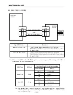
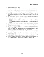
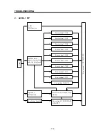
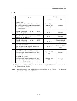
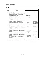
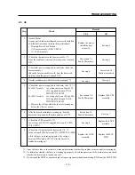
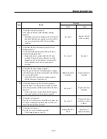
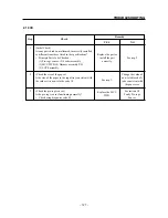
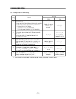
2.2 U2
Step
Check
Remedy
YES
NO
1
(Initial Check)
Are any parts broken, malformed, incorrectly installed
or different from those listed in the specifications?
• Principle Parts to be Checked:
(1) ROS assembly, (2) MCU PWB
(3) LVPS assembly, (4) CRU sensor PWB
(5) CRU actuator, (6) EP toner cartridge
(7) ROS harness assembly
(8) CRU harness assembly
2
(Check the data in the non-volatile memory.)
Is the value of non-volatile code 1 correctly set?
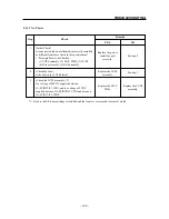
3
(Check the scanner assembly in the ROS assembly.) *1
Is the scanner motor in the ROS assembly running
when test print mode is entered?
• Listen to the sound of the rotating motor just before
the U2 error occurs.
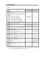
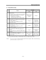
4
(Check the LD power in the LD assembly of the ROS
assembly.) *2
Is a voltage of 5 VDC supplied between P12-1PIN
↔
P12-3PIN?
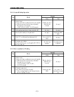
5
(Check the LD power in the LD assembly of the ROS
assembly.) *2
Is a voltage of 5VD supplied between P17-4PIN
↔
P/J17-PIN?
*1: When it is difficult to hear the sound of the rotating motor, disconnect connector P/J14 on the drive assembly
and stop the main motor in order to hear the sound of the motor better.
*2: Be sure that the EP toner cartridge is installed and the front cover assembly is securely closed.
Change the value of
the non-volatile code
to the correct setting.
See step 3.
See section 3.4
Faulty ROS Assem-
bly.
See step 5.
Replace the part or
install the part
correctly.
See step 2.
See step 4.
See section 3.3
Faulty Scanner
Assembly.
See section 3.9
Faulty LD Switch.
See section 3.1
Faulty LVPS
Assembly 5VDC.
Summary of Contents for WinType 4000
Page 1: ...WinType 4000 TECHNICAL MANUAL SECOND EDITION LASER PRINTER ...
Page 4: ......
Page 6: ... 2 GENERAL SPECIFICATIONS ...
Page 14: ... 10 THEORY OF OPERATION ...
Page 26: ... 22 THEORY OF OPERATION Figure 2 9 Electrical ...
Page 28: ... 24 REPLACEMENT AND ADJUSTMENT OF PARTS ...
Page 62: ... 58 REPLACEMENT AND ADJUSTMENT OF PARTS ...
Page 64: ... 60 MAINTENANCE GUIDE ...
Page 114: ... 110 MAINTENANCE GUIDE ...
Page 116: ... 112 TROUBLESHOOTING ...
Page 176: ... 172 5 ELECTRICAL 5 1 Disassembly Drawing 1 2 3 4 14 4 14 2 14 1 14 3 13 12 11 6 5 7 8 9 10 ...
Page 179: ......


