


– 100 –
MAINTENANCE GUIDE
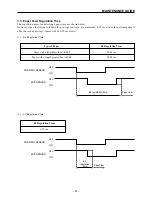
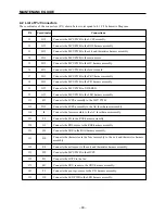
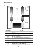
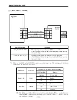
Signal Wire Name
Reference
TR-D/A ON(L) 5VDC
This is the output signal for both sides of the TR.
TR-A/D ON(L) 5.1VDC
This signal converts the TR output current that flows to the TR into a
voltage.
TR(–)
This signal controls the DC voltage sent from the HVPS to the BTR.
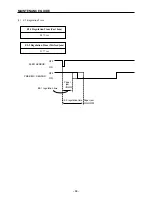
DB ON(L) 24VDC
This is the DB output signal. (It outputs both DC and AC components.)
CR-DC
This is the DC signal from the HVPS to the CR.
CR-AC
This is the AC signal from the HVPS to the CR.
TR
This signal is the output from the HVPS to the BTR.
* TR(–) is output during the transfer process and TR(+) is output while
cleaning of the BTR is taking place.
DB
This signal is the output from the HVPS to the magnetic roller. (Devel-
oping Bias)
CR
This signal is the output from the HVPS to the CR.
FAN ON(L) 5VDC
This signal controls the ON/OFF position of the fan according to the
remote signal.
The fan is turned ON when the signal is low.
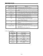
*1: Rated Output of the HVPS
Output Name
Rated Output
CR(AC)
220
µ
A (f=160Hz)
CR(DC)
–350V
TR(+)
0 ~ 3kV
TR(–)
–600VDC
DB(AC)
1.7kVp-p (f=2.4kHz)
DB(DC)
–210VDC
Summary of Contents for WinType 4000
Page 1: ...WinType 4000 TECHNICAL MANUAL SECOND EDITION LASER PRINTER ...
Page 4: ......
Page 6: ... 2 GENERAL SPECIFICATIONS ...
Page 14: ... 10 THEORY OF OPERATION ...
Page 26: ... 22 THEORY OF OPERATION Figure 2 9 Electrical ...
Page 28: ... 24 REPLACEMENT AND ADJUSTMENT OF PARTS ...
Page 62: ... 58 REPLACEMENT AND ADJUSTMENT OF PARTS ...
Page 64: ... 60 MAINTENANCE GUIDE ...
Page 114: ... 110 MAINTENANCE GUIDE ...
Page 116: ... 112 TROUBLESHOOTING ...
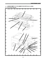
Page 176: ... 172 5 ELECTRICAL 5 1 Disassembly Drawing 1 2 3 4 14 4 14 2 14 1 14 3 13 12 11 6 5 7 8 9 10 ...
Page 179: ......