


– 12 –
THEORY OF OPERATION
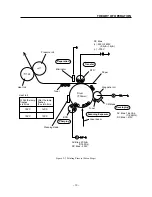
• Description of the Printing Process
Step
Details
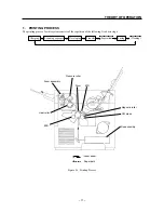
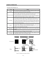
Charging
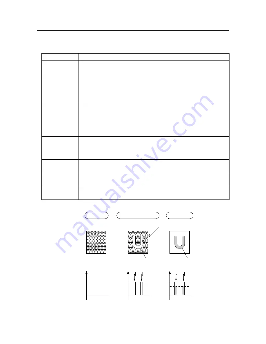
The surface of the rotating drum in the EP toner cartridge is uniformly negatively charged
by the electric charge from the BCR (Bias Charge Roller).
The ROS assembly scans the exposure by converting the image signal from the MCU PWB
into an optical signal (laser beam) and directs the laser beam onto the drum.
Scanning Exposure
When an image is present, a laser is emitted and the laser beam is irradiated onto the surface
of the drum causing the irradiated area to be set to a neutral charge, thus enabling an
invisible latent electrostatic image to be formed on the drum’s surface.
The latent electrostatic image on the drum’s surface attracts toner from the surface of the
magnetic roller in the EP toner cartridge, forming a visible image on the surface of the drum.
Developing
The magnet inside the magnetic roller causes the toner, which also has magnetic properties,
to adhere to the roller while the friction between the rotating magnetic roller and the CM
blade (Charge Metal Blade) negatively charges the toner, so that a thin layer of toner is n
the surface of the magnetic roller.
Transfer
A positive charge is applied to the back of the paper by the BTR (Bias Transfer Roller)
causing the toner on the drum’s surface to be transferred to the paper.
Applying a positive charge to the back of the paper causes the paper itself to be positively
charged, so that the paper adheres to the drum
(Separation)
The firmness of the paper causes the paper with the toner affixed to it to be separated from
the drum.
Fusing
The heat from the heat roller heated by the heat rod and the pressure from the pressure roller
causes the toner to be fused to the paper in the fuser assembly.
(Cleaning)
Any residual toner remaining on the drum after the transfer step is scraped off by the
cleaning blade which is in contact with the drum’s surface.
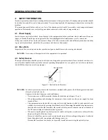
–350V
0
–V
–350V
0
–V
–350V
0
–V
–210V
(Developing bias)
Laser beam
Scanning Exposure
Developing
Charging
Toner image
(Visible image)
Electrostatic latent
image (Invisible image)
Drum’s surface
Voltage
Figure 2-2 Printing Process (Drum’s Surface)
Summary of Contents for WinType 4000
Page 1: ...WinType 4000 TECHNICAL MANUAL SECOND EDITION LASER PRINTER ...
Page 4: ......
Page 6: ... 2 GENERAL SPECIFICATIONS ...
Page 14: ... 10 THEORY OF OPERATION ...
Page 26: ... 22 THEORY OF OPERATION Figure 2 9 Electrical ...
Page 28: ... 24 REPLACEMENT AND ADJUSTMENT OF PARTS ...
Page 62: ... 58 REPLACEMENT AND ADJUSTMENT OF PARTS ...
Page 64: ... 60 MAINTENANCE GUIDE ...
Page 114: ... 110 MAINTENANCE GUIDE ...
Page 116: ... 112 TROUBLESHOOTING ...
Page 176: ... 172 5 ELECTRICAL 5 1 Disassembly Drawing 1 2 3 4 14 4 14 2 14 1 14 3 13 12 11 6 5 7 8 9 10 ...
Page 179: ......


