


– 47 –
REPLACEMENT AND ADJUSTMENT OF PARTS
Be sure that the power is disconnected!
4.
ROS
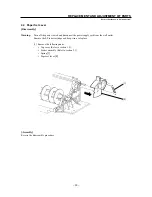
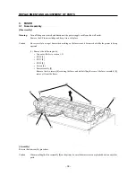
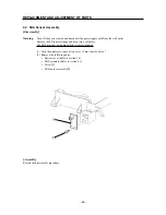
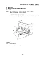
4.1 ROS Assembly
[Disassembly]
Warning:
Turn off the power switch and disconnect the power supply cord from the wall outlet.
Remove the EP toner cartridge and keep it in a safe place.
The ROS must not be running while it is being handled.
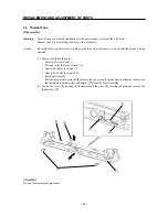
(1) Turn the printer over onto its top cover. (Turn it upside down.)
(2) Remove the bottom cover. (Refer to section 1.4)
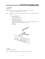
(3) Disconnect CN122
[1]
from the scanner assembly
[2]
.
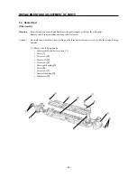
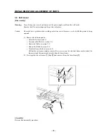
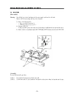
(4) Disconnect CN121
[3]
from the laser diode
[4]
.
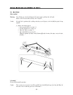
(5) Disconnect CN123
[5]
from the SOS sensor assembly
[6]
.
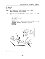
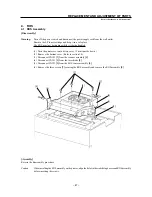
(6) Remove the three screws
[7]
securing the ROS assembly and remove the ROS assembly
[8]
.
[Assembly]
Reverse the disassembly procedure.
Caution:
When installing the ROS assembly on the printer, align the holes in the stabilizing bosses and ROS assembly
before inserting the screws.
[8]
[2]
[7]
[4]
[3]
[6]
[5]
[1]
Summary of Contents for WinType 4000
Page 1: ...WinType 4000 TECHNICAL MANUAL SECOND EDITION LASER PRINTER ...
Page 4: ......
Page 6: ... 2 GENERAL SPECIFICATIONS ...
Page 14: ... 10 THEORY OF OPERATION ...
Page 26: ... 22 THEORY OF OPERATION Figure 2 9 Electrical ...
Page 28: ... 24 REPLACEMENT AND ADJUSTMENT OF PARTS ...
Page 62: ... 58 REPLACEMENT AND ADJUSTMENT OF PARTS ...
Page 64: ... 60 MAINTENANCE GUIDE ...
Page 114: ... 110 MAINTENANCE GUIDE ...
Page 116: ... 112 TROUBLESHOOTING ...
Page 176: ... 172 5 ELECTRICAL 5 1 Disassembly Drawing 1 2 3 4 14 4 14 2 14 1 14 3 13 12 11 6 5 7 8 9 10 ...
Page 179: ......


