D
D:26
Shock pulse measurement
In addition to the basic input data, one can set values for
COMP and ACCUM.
ACCUM
(accumulation) determines the number of measuring
cycles before the Leonova displays the average value as
result. ACCUM can be set from 1 to 9. Especially on bearings
with a low rpm, set ACCUM to at least 3.
COMP
(compensation number) is used to calibrate the
measuring point, normally to compensate for a somewhat
weaker signal from a measuring point that does not quite
comply with the SPM rules. To find the correct COMP no.,
use the LUBMASTER function in Condmaster
®
.
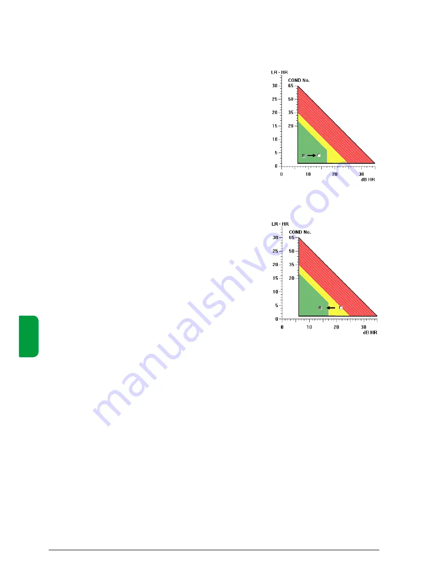
A normal signal from a good bearing should be near the
centre of the green part of the evaluation frame. If it is far
to the left, you can ”push it forward” by setting a COMP no.
If the signal is outside of the left side of evaluation frame,
Leonova will display the error code E3 = signal too low.
The COMP no. is added to the measuring result before it
is evaluated. Thus, it will influence the evaluation results
CODE, LUB, and COND, but not the displayed values for
HR and LR.
It is possible to set negative COMP nos., but you should
avoid that. With a positive COMP no., you make the evalua-
tion results worse than apparent from the measured LR/HR
values. With a negative COND. no., you ‘improve’ bearing
condition, which can have unpleasant consequences if you
are wrong in assuming that the signal from this bearing is
stronger than normal. To avoid alarm from a stable bearing
with high readings, it is better to change the alarm levels.
Positive
COMP
Accumulation and compensation
Negative
COMP
Summary of Contents for leonova emerald
Page 1: ...User guide PORTABLE EFFICIENCY ...
Page 2: ......
Page 6: ...A 2 General instrument functions A ...
Page 36: ...B 2 General measurement functions B ...
Page 74: ...C 2 Measurement techniques always included B C ...
Page 88: ...D D 2 Shock pulse measurement ...
Page 122: ...D D 36 Shock pulse measurement ...
Page 124: ...E E 2 Vibration measurement ...
Page 150: ...E E 28 Vibration measurement ...
Page 152: ...F F 2 Rotor balancing ...
Page 170: ...F F 20 Rotor balancing ...


