21
Wiring (continued)
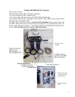
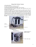
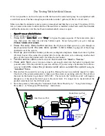
Mount the main power terminals or junction box on a bulkhead adjacent to the feed pump
module. Make sure that this is a dry location well above bilge level and not subject to water
spray.
Route the
control cable
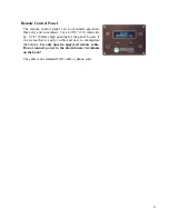
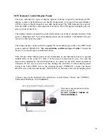
through the boat to the MPC display location. Be careful not to
damage the connector. Plug this into the back of the display.
Route the
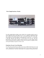
Clark pump harness
to the high pressure pump location. Plug in the salinity sen-
sor cable and install the plastic boot over the connection. Plug in the rotoflow meter and wa-
ter proof the plug with the supplied heat shrink tubing. Locate the diversion valve wires and
splice the remaining two conductor cables with the supplied butt splices. These are heat
shrink connectors so you can seal them after splicing.
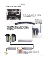
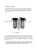
Route the single two conductor cable to the fresh water flush module and splice the wires to
the solenoid wires. Heat the splice for sealing.
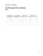
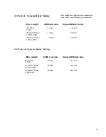
Check the wire size chart to select the proper size power feed to the main power harness. DC
power feeds should be uninterruptible so as not to lose the microprocessors memory during
storage cycle. Avoid house breaker panels that could be easily tripped.
DC Systems:
•
Install a 30Amp breaker at source and size the wiring for 25Amperes.
•
Provide circuit protection at the source! Inadequate wiring will cause a loss of system per-
formance. DC power should be uninterruptible.
Note: If the specified circuit breaker sizes are unavailable use the next higher rating
but do not exceed the specification by more then 10%. All wiring to be done to
applicable ABYC, Marine UL or CE standards.
Summary of Contents for Newport 1000
Page 2: ...2...
Page 4: ...4...
Page 6: ...6...
Page 8: ...8...
Page 38: ...38 Push the Auto Flush button press Stop press Auto Flush again...
Page 59: ...59 Z BRANE OPERATION MANUAL...

