


2-21
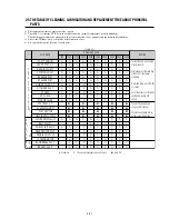
1) The replacement time of parts is not life of parts.
2) The table 2-1 is that the VCR Set is in normal condition (normal temperature, normal humidity).
The checking period may be changed owing to the condition of use, runtime and environmental conditions.
3) Life of the Cylinder Ass’y is depend on the condition of use.
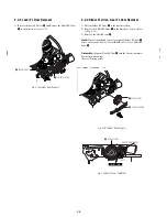
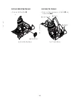
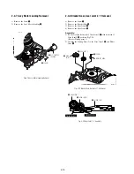
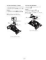
4) See exploded view for location of each parts.
<Table 2-1>
∆
: Cleaning O : Check and replacement in necessary
◆
: Add Oil
T
A
P
E
P
A
T
H
S
Y
S
T
E
M
D
R
I
V
I
N
G
*
Parts Name
Checking Period
Remark
500
1000
1500
2000
2500
3000
3500
4000
4500
5000
POST TENSION
∆
∆
∆
∆
∆
∆
∆
∆
∆
∆
SLANT POST S, T
∆
∆
∆
∆
∆
∆
∆
∆
∆
∆
#8 GUIDE SHAFT
∆
∆
∆
∆
∆
∆
∆
∆
∆
∆
CAPSTAN SHAFT
∆
∆
∆
∆
∆
∆
∆
∆
∆
∆
#9 GUIDE POST
∆
∆
∆
∆
∆
∆
∆
∆
∆
∆
#3 GUIDE POST
∆
∆
∆
∆
∆
∆
∆
∆
∆
∆
GUIDE ROLLER S, T
∆
∆
∆
O
O
O
O
O
O
O
CYLINDER ASS’Y
∆
O
O
O
O
O
O
O
O
O
FE HEAD
∆
∆
∆
O
O
O
O
O
O
O
ACE HEAD
∆
O
O
O
O
O
O
O
O
O
PINCH ROLLER
∆
O
O
O
O
O
O
O
O
O
POST REEL S, T
◆
◆
◆
◆
◆
SLEEVE TENSION
◆
◆
◆
◆
◆
POST CENTER
◆
◆
◆
◆
◆
LEVER IDLE BOSS (2Point)
◆
◆
◆
◆
◆
CAPSTAN MOTOR PULLEY
∆
∆
∆
∆
∆
O
O
O
O
O
BELT PULLEY
O
O
O
O
O
O
O
HOLDER CLUTCH ASS’Y
∆
O
O
O
O
O
O
O
O
O
GEAR CENTER ASS’Y
O
O
O
O
O
O
O
O
O
GEAR IDLE (2Point)
O
O
O
O
O
O
O
O
O
LOADING MOTOR
O
O
O
O
O
O
O
O
O
BAND BRAKE ASS’Y
O
O
O
O
O
O
O
O
O
BRAKE T ASS’Y
O
O
O
O
O
O
O
O
O
S
Y
S
T
E
M
- Periodic time of applying oil
(Apply oil after cleaning)
- The excessive applying oil may
be the cause of malfunction.
- To clean the parts, use patch and
alcohol (solvent).
- After cleaning, use the video tape
after alcohol is gone away
completely.
- We recommend to use oil [EP-50]
or solvent.
- One or two drops of oil should be
applied after cleaning with
alcohol.
B
R
A
K
E
S
Y
S
T
E
M
2-5 THE TABLE OF CLEANING, LUBRICATION AND REPLACEMENT TIME ABOUT PRINCIPAL
PARTS
Summary of Contents for RDR VX555 - DVDr/ VCR Combo
Page 62: ...2 22 2 22E MEMO ...
Page 64: ...3 4E MEMO ...
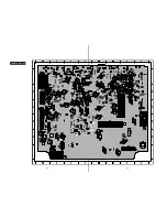
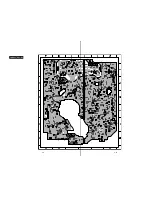
Page 66: ...4 1 DVD Main PCB 4 4 4 3 COMPONENT SIDE ...
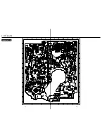
Page 67: ...4 6 4 5 CONDUCTOR SIDE ...
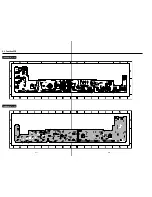
Page 68: ...4 8 4 7 4 2 VCR Main PCB COMPONENT SIDE ...
Page 69: ...4 10 4 9 CONDUCTOR SIDE ...
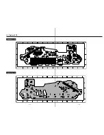
Page 70: ...4 12 4 11 4 3 Function PCB COMPONENT SIDE COMPONENT SIDE ...
Page 71: ...4 14 4 13 4 4 Front Jack PCB COMPONENT SIDE CONDUCTOR SIDE ...
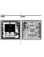
Page 72: ...4 16E 4 15 4 5 DV Jack PCB COMPONENT SIDE COMPONENT SIDE ...
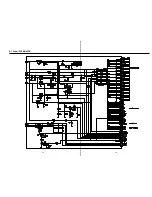
Page 74: ...5 4 5 3 5 1 S M P S VCR Main PCB ...
Page 75: ...5 6 5 5 5 2 Power VCR Main PCB ...
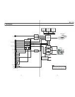
Page 76: ...5 8 5 7 5 3 Logic VCR Main PCB ...
Page 77: ...5 10 5 9 5 4 A V VCR Main PCB ...
Page 78: ...5 12 5 11 5 5 Hi Fi VCR Main PCB ...
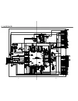
Page 79: ...5 14 5 13 5 6 MPEG Decoder DVD Main PCB ...
Page 80: ...5 16 5 15 5 7 A V Decoder DVD Main PCB ...
Page 81: ...5 18 5 17 5 8 In Out DVD Main PCB ...
Page 82: ...5 20 5 19 5 9 DV HDMI DVD Main PCB ...
Page 83: ...5 22 5 21 5 10 Front Timer Front Jack PCB DV Jack DV Jack PCB ...
Page 84: ...5 24E 5 23 5 11 Function Function PCB ...
Page 127: ...MEMO ...


