


— 2 —
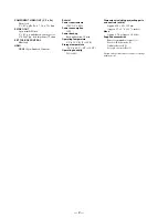
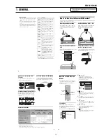
COMPONENT VIDEO OUT (Y, P
B
, P
R
)
Phono jack
Y: 1.0 Vp-p/P
B
, P
R
: 0.7 Vp-p, 75 ohms
S VIDEO OUT
4-pin, mini-DIN jack
Y: 1.0 Vp-p, unbalanced, sync negative
C: 0.286 Vp-p, load impedance 75 ohms
SET TOP BOX CONTROL
Mini jack
HDMI
HDMI 19 pin-Standard Connector
General
Power requirements
120 V AC, 60 Hz
Power consumption
31 W
Power back-up
Back-up duration: 30 min
Operating temperature
5
°
C to 35
°
C (41
°
F to 95
°
F)
Storage temperature
–20
°
C to 60
°
C (–4
°
F to 140
°
F)
Operating humidity
25% to 80%
Dimensions including projecting parts
and controls (w/h/d)
Approx. 430
×
82
×
332 mm
(Approx. 17
×
3
1
/
4
×
13
1
/
8
inches)
Mass
Approx. 4.7 kg (Approx. 10.4 lbs)
Supplied accessories
Remote commander (remote) (1)
Size AA (R6) batteries (2)
Audio/video cord (1)
Set top box controller (1)
Design and specifications are subject to change
without notice.
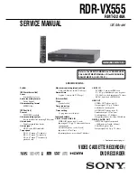
Summary of Contents for RDR VX555 - DVDr/ VCR Combo
Page 62: ...2 22 2 22E MEMO ...
Page 64: ...3 4E MEMO ...
Page 66: ...4 1 DVD Main PCB 4 4 4 3 COMPONENT SIDE ...
Page 67: ...4 6 4 5 CONDUCTOR SIDE ...
Page 68: ...4 8 4 7 4 2 VCR Main PCB COMPONENT SIDE ...
Page 69: ...4 10 4 9 CONDUCTOR SIDE ...
Page 70: ...4 12 4 11 4 3 Function PCB COMPONENT SIDE COMPONENT SIDE ...
Page 71: ...4 14 4 13 4 4 Front Jack PCB COMPONENT SIDE CONDUCTOR SIDE ...
Page 72: ...4 16E 4 15 4 5 DV Jack PCB COMPONENT SIDE COMPONENT SIDE ...
Page 74: ...5 4 5 3 5 1 S M P S VCR Main PCB ...
Page 75: ...5 6 5 5 5 2 Power VCR Main PCB ...
Page 76: ...5 8 5 7 5 3 Logic VCR Main PCB ...
Page 77: ...5 10 5 9 5 4 A V VCR Main PCB ...
Page 78: ...5 12 5 11 5 5 Hi Fi VCR Main PCB ...
Page 79: ...5 14 5 13 5 6 MPEG Decoder DVD Main PCB ...
Page 80: ...5 16 5 15 5 7 A V Decoder DVD Main PCB ...
Page 81: ...5 18 5 17 5 8 In Out DVD Main PCB ...
Page 82: ...5 20 5 19 5 9 DV HDMI DVD Main PCB ...
Page 83: ...5 22 5 21 5 10 Front Timer Front Jack PCB DV Jack DV Jack PCB ...
Page 84: ...5 24E 5 23 5 11 Function Function PCB ...
Page 127: ...MEMO ...


