


— 3 —
WARNING!!
WHEN SERVICING, DO NOT APPROACH THE LASER
EXIT WITH THE EYE TOO CLOSELY. IN CASE IT IS
NECESSARY TO CONFIRM LASER BEAM EMISSION,
BE SURE TO OBSERVE FROM A DISTANCE OF MORE
THAN 25 cm FROM THE SURFACE OF THE
OBJECTIVE LENS ON THE OPTICAL PICK-UP BLOCK.
CAUTION
Use of controls or adjustments or performance of procedures
other than those specified herein may result in hazardous
radiation exposure.
SAFETY-RELATED COMPONENT WARNING!!
COMPONENTS IDENTIFIED BY MARK
0
OR DOTTED
LINE WITH MARK
0
ON THE SCHEMATIC DIAGRAMS
AND IN THE PARTS LIST ARE CRITICAL TO SAFE
OPERATION. REPLACE THESE COMPONENTS WITH
SONY PARTS WHOSE PART NUMBERS APPEAR AS
SHOWN IN THIS MANUAL OR IN SUPPLEMENTS
PUBLISHED BY SONY.
CAUTION:
The use of optical instrument with this product will increase eye
hazard.
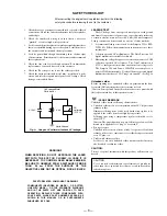
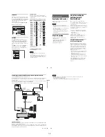
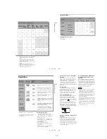
Fig. A.
Using an AC voltmeter to check AC leakage.
1.5 k
Ω
0.15
µ
F
AC
voltmeter
(0.75 V)
To Exposed Metal
Parts on Set
Earth Ground
LEAKAGE TEST
The AC leakage from any exposed metal part to earth ground
and from all exposed metal parts to any exposed metal part having
a return to chassis, must not exceed 0.5 mA (500 microamperes).
Leakage current can be measured by any one of three methods.
1. A commercial leakage tester, such as the Simpson 229 or RCA
WT-540A. Follow the manufacturers' instructions to use these
instruments.
2. A battery-operated AC milliammeter. The Data Precision 245
digital multimeter is suitable for this job.
3. Measuring the voltage drop across a resistor by means of a VOM
or battery-operated AC voltmeter. The “limit” indication is
0.75V, so analog meters must have an accurate low-voltage scale.
The Simpson 250 and Sanwa SH-63Trd are examples of a
passive VOM that is suitable. Nearly all battery operated digital
multimeters that have a 2V AC range are suitable. (See Fig. A)
1. Check the area of your repair for unsoldered or poorly-soldered
connections. Check the entire board surface for solder splashes
and bridges.
2. Check the interboard wiring to ensure that no wires are
“pinched” or contact high-wattage resistors.
3. Look for unauthorized replacement parts, particularly transistors,
that were installed during a previous repair. Point them out to
the customer and recommend their replacement.
4. Look for parts which, though functioning, show obvious signs
of deterioration. Point them out to the customer and recommend
their replacement.
5. Check the line cord for cracks and abrasion. Recommend the
replacement of any such line cord to the customer.
6. Check the B+ voltage to see it is at the values specified.
7. Check the antenna terminals, metal trim, “metallized” knobs,
screws, and all other exposed metal parts for AC leakage. Check
leakage as described below.
SAFETY CHECK-OUT
After correcting the original service problem, perform the following
safety checks before releasing the set to the customer:
Unleaded solder
Boards requiring use of unleaded solder are printed with the lead-
free mark (LF) indicating the solder contains no lead.
(Caution: Some printed circuit boards may not come printed with
the lead free mark due to their particular size.)
: LEAD FREE MARK
Unleaded solder has the following characteristics.
•
Unleaded solder melts at a temperature about 40
°
C higher than
ordinary solder.
Ordinary soldering irons can be used but the iron tip has to be
applied to the solder joint for a slightly longer time.
Soldering irons using a temperature regulator should be set to
about 350
°
C.
Caution: The printed pattern (copper foil) may peel away if the
heated tip is applied for too long, so be careful!
•
Strong viscosity
Unleaded solder is more viscous (sticky, less prone to flow) than
ordinary solder so use caution not to let solder bridges occur such
as on IC pins, etc.
•
Usable with ordinary solder
It is best to use only unleaded solder but unleaded solder may
also be added to ordinary solder.
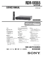
Summary of Contents for RDR VX555 - DVDr/ VCR Combo
Page 62: ...2 22 2 22E MEMO ...
Page 64: ...3 4E MEMO ...
Page 66: ...4 1 DVD Main PCB 4 4 4 3 COMPONENT SIDE ...
Page 67: ...4 6 4 5 CONDUCTOR SIDE ...
Page 68: ...4 8 4 7 4 2 VCR Main PCB COMPONENT SIDE ...
Page 69: ...4 10 4 9 CONDUCTOR SIDE ...
Page 70: ...4 12 4 11 4 3 Function PCB COMPONENT SIDE COMPONENT SIDE ...
Page 71: ...4 14 4 13 4 4 Front Jack PCB COMPONENT SIDE CONDUCTOR SIDE ...
Page 72: ...4 16E 4 15 4 5 DV Jack PCB COMPONENT SIDE COMPONENT SIDE ...
Page 74: ...5 4 5 3 5 1 S M P S VCR Main PCB ...
Page 75: ...5 6 5 5 5 2 Power VCR Main PCB ...
Page 76: ...5 8 5 7 5 3 Logic VCR Main PCB ...
Page 77: ...5 10 5 9 5 4 A V VCR Main PCB ...
Page 78: ...5 12 5 11 5 5 Hi Fi VCR Main PCB ...
Page 79: ...5 14 5 13 5 6 MPEG Decoder DVD Main PCB ...
Page 80: ...5 16 5 15 5 7 A V Decoder DVD Main PCB ...
Page 81: ...5 18 5 17 5 8 In Out DVD Main PCB ...
Page 82: ...5 20 5 19 5 9 DV HDMI DVD Main PCB ...
Page 83: ...5 22 5 21 5 10 Front Timer Front Jack PCB DV Jack DV Jack PCB ...
Page 84: ...5 24E 5 23 5 11 Function Function PCB ...
Page 127: ...MEMO ...


