


2-20
1
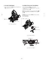
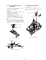
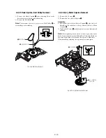
ASS'Y POST #8 GUIDE
Fig. 2-40 Ass’y Post #8 Guide Removal
2-4-27 Ass’y Post #8 Guide Removal
1) Rotate the Ass’y Post #8 Guide
1
in the direction of arrow to
lift up.
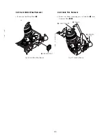
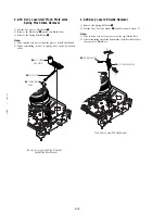
2-4-28 Ass’y Level Head Cleaner Removal
1) Release the Hook
1
.
2) Lift the Ass’y Lever Head Cleaner
2
.
Fig. 2-41 Ass’y Lever Head Cleaner Removal
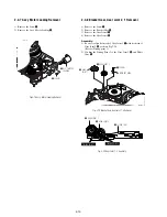
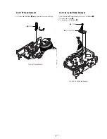
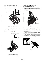
2-4-29 How to Eject the Cassette Tape
(If the tape is stuck in the unit)
1) Turn the Gear worm
1
clockwise with screw driver.(Refer to
arrow)
(Other method: Remove the Screw of Ass’y Motor Load,
Separate the Ass’y Motor Load)
Fig. 2-42
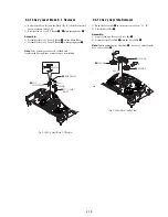
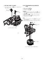
2) When Slider S,T are approched in the position of unloading,
rotate holder Clutch counterclockwise after inserting screw driver
in the hole of frame's bottom in order to wind the unwinded
tape.
(Refer to Fig.2-43)
(If you rotate Gear Worm
1
continuously when tape is in state
of unwinding, you may cause a tape contamination by grease
and tape damage.
Be sure to wind the unwinded tape in the state of set horizently.)
3) Rotate Gear Worm
1
clockwise using screw driver again up to
the state of eject mode and then pick out the tape.(Refer to Fig.2-
42)
Fig. 2-43
FRAME
1
HOOK
2
ASS'Y LEVER HEAD CLEANER
1
GEAR WORM
Summary of Contents for RDR VX555 - DVDr/ VCR Combo
Page 62: ...2 22 2 22E MEMO ...
Page 64: ...3 4E MEMO ...
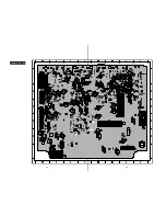
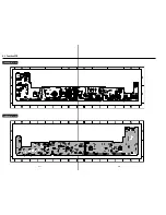
Page 66: ...4 1 DVD Main PCB 4 4 4 3 COMPONENT SIDE ...
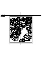
Page 67: ...4 6 4 5 CONDUCTOR SIDE ...
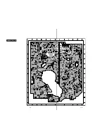
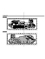
Page 68: ...4 8 4 7 4 2 VCR Main PCB COMPONENT SIDE ...
Page 69: ...4 10 4 9 CONDUCTOR SIDE ...
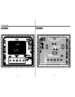
Page 70: ...4 12 4 11 4 3 Function PCB COMPONENT SIDE COMPONENT SIDE ...
Page 71: ...4 14 4 13 4 4 Front Jack PCB COMPONENT SIDE CONDUCTOR SIDE ...
Page 72: ...4 16E 4 15 4 5 DV Jack PCB COMPONENT SIDE COMPONENT SIDE ...
Page 74: ...5 4 5 3 5 1 S M P S VCR Main PCB ...
Page 75: ...5 6 5 5 5 2 Power VCR Main PCB ...
Page 76: ...5 8 5 7 5 3 Logic VCR Main PCB ...
Page 77: ...5 10 5 9 5 4 A V VCR Main PCB ...
Page 78: ...5 12 5 11 5 5 Hi Fi VCR Main PCB ...
Page 79: ...5 14 5 13 5 6 MPEG Decoder DVD Main PCB ...
Page 80: ...5 16 5 15 5 7 A V Decoder DVD Main PCB ...
Page 81: ...5 18 5 17 5 8 In Out DVD Main PCB ...
Page 82: ...5 20 5 19 5 9 DV HDMI DVD Main PCB ...
Page 83: ...5 22 5 21 5 10 Front Timer Front Jack PCB DV Jack DV Jack PCB ...
Page 84: ...5 24E 5 23 5 11 Function Function PCB ...
Page 127: ...MEMO ...


