


2-14
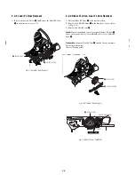
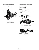
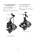
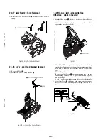
2-4-15 Disk S, T Reel Removal
1) Lift the Disk S, T Reel
1
,
2
.
Fig. 2-27 Disk S, T Reel Removal
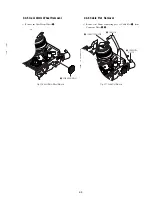
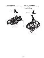
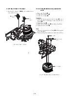
2-4-16 Ass’y Holder Clutch Removal
1) Remove the Washer Slit
1
.
2) Lift the Ass’y Holder Clutch
2
.
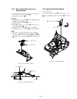
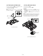
Note:
When you reinstall Ass’y Holder Clutch.
1) Check the condition of spring as shown in detail A.
2) Don't push Ass’y Holder Clutch down with excessive force Just
insert Holder Clutch Ass’y into post center with dead force and
Rotate it smoothly.
Be sure to confirm that spring is in the slit of Ass’y Gear Center
as shown in detail B.
Fig. 2-28 Ass’y Holder Clutch Removal
1
WASHER SLIT
2
ASS
'
Y HOLDER CLUTCH
DETAIL A
<BAD>
SPRING
<GOOD>
<BAD>
SPRING
<GOOD>
DETAIL B
1
REEL S
2
REEL T
Summary of Contents for RDR VX555 - DVDr/ VCR Combo
Page 62: ...2 22 2 22E MEMO ...
Page 64: ...3 4E MEMO ...
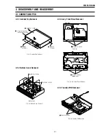
Page 66: ...4 1 DVD Main PCB 4 4 4 3 COMPONENT SIDE ...
Page 67: ...4 6 4 5 CONDUCTOR SIDE ...
Page 68: ...4 8 4 7 4 2 VCR Main PCB COMPONENT SIDE ...
Page 69: ...4 10 4 9 CONDUCTOR SIDE ...
Page 70: ...4 12 4 11 4 3 Function PCB COMPONENT SIDE COMPONENT SIDE ...
Page 71: ...4 14 4 13 4 4 Front Jack PCB COMPONENT SIDE CONDUCTOR SIDE ...
Page 72: ...4 16E 4 15 4 5 DV Jack PCB COMPONENT SIDE COMPONENT SIDE ...
Page 74: ...5 4 5 3 5 1 S M P S VCR Main PCB ...
Page 75: ...5 6 5 5 5 2 Power VCR Main PCB ...
Page 76: ...5 8 5 7 5 3 Logic VCR Main PCB ...
Page 77: ...5 10 5 9 5 4 A V VCR Main PCB ...
Page 78: ...5 12 5 11 5 5 Hi Fi VCR Main PCB ...
Page 79: ...5 14 5 13 5 6 MPEG Decoder DVD Main PCB ...
Page 80: ...5 16 5 15 5 7 A V Decoder DVD Main PCB ...
Page 81: ...5 18 5 17 5 8 In Out DVD Main PCB ...
Page 82: ...5 20 5 19 5 9 DV HDMI DVD Main PCB ...
Page 83: ...5 22 5 21 5 10 Front Timer Front Jack PCB DV Jack DV Jack PCB ...
Page 84: ...5 24E 5 23 5 11 Function Function PCB ...
Page 127: ...MEMO ...


