


1-6
27
Ho
o
kup
s a
nd Set
tings
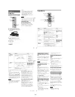
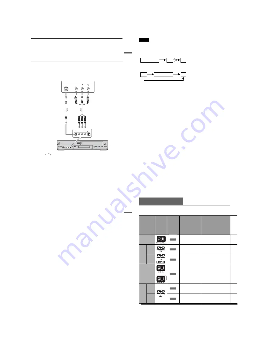
Connecting Another VCR or Similar Device
After disconnecting the recorder’s power cord from an AC outlet, connect the other VCR or similar
recording device to the LINE IN jacks of this recorder. See also the instruction manual supplied with the
connected equipment.
If you connect equipment that has a timer function, you can use the Synchro Rec function (pages 51 and
80). In this case, connect the equipment to the LINE 1 IN jacks (page 13).
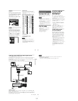
Connecting to the LINE 2 IN jacks on the front panel
Connect other VCR or similar device to the LINE 2 IN jacks of this recorder. If the equipment has an
S video jack, you can use an S video cord (not supplied) instead of the yellow (video) plug of the audio/
video cord. Do not connect to the S VIDEO and yellow VIDEO jacks at the same time.
You can connect a second DVD player and record DVDs.
z
Hints
• When the connected equipment outputs only monaural sound, connect an audio cord to the white LINE IN AUDIO L
(mono) jack.
• To record from connected equipment, select an input source (LINE1 or LINE2) to match the jack you connected to
(pages 54 and 83).
S VIDEO
AUDIO
L
R
VIDEO
(MONO)
DV IN
S VIDEO
VIDEO
LINE 2 IN
L AUDIO R
OUTPUT
Other VCR, etc.
S video cord
(not supplied)
Audio/video cord
(not supplied)
VCR-DVD recorder
to LINE 2 IN
: Signal flow
,
continued
28
Notes
• Do not connect more than one type of video cord between the recorder and your TV at the same time.
• Pictures containing copy protection signals that prohibit any copying cannot be recorded. You cannot dub from DVD
VIDEOs to this recorder.
• Do not connect the output jack of this recorder to another equipment’s input jack with the other equipment’s output
jack connected to the input jack of this recorder. Noise (feedback) may result.
• If you pass the recorder signals via the VCR, you may not receive a clear image on your TV screen.
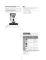
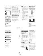
Be sure to connect your VCR to the VCR-DVD recorder and your TV in the order shown below. To watch video tapes,
watch the tapes through a second line input on your TV.
VCR
VCR-DVD recorder
TV
VCR
VCR-DVD recorder
TV
Line input 1
Line input 2
29
Ho
o
kup
s
an
d
S
e
tt
in
g
s
30
Quick Guide to Disc Types
Recordable and Playable Discs
Usable disc versions (as of December 2006)
• 8×-speed or slower DVD+RWs
• 6×-speed or slower DVD-RWs (Ver.1.1, Ver.1.2
with CPRM
*1
)
• 16×-speed or slower DVD+Rs
• 16×-speed or slower DVD-Rs (Ver.2.0, Ver.2.1
with CPRM)
• 8×-speed or slower DVD+R DL (Double Layer)
discs
*6
“DVD+RW,” “DVD-RW,” “DVD+R,” “DVD+R DL,”
and “DVD-R” logos are trademarks.
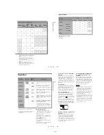
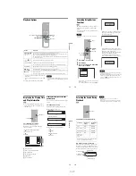
Disc Type
Disc
Logo
Icon used
in this
manual
Formatting
(new discs)
Compatibility with other
DVD players (finalizing)
DVD+RW
Automatically
formatted
Playable on DVD+RW
compatible players
(automatically finalized)
DVD-
RW
VR
mode
Format in VR mode
*2
(page 47)
Playable only on VR mode
compatible players (finalization
unnecessary) (page 88)
Video
mode
Format in Video
mode
*2
(page 47)
Playable on most DVD players
(finalization necessary)
(page 88)
DVD+R
Automatically
formatted
Playable on DVD+R compatible
players (finalization necessary)
(page 88)
DVD+R DL
DVD-
R
VR
mode
Format in VR mode
using the “Disc Setting”
display (page 67)
Playable only on DVD-R VR
mode compatible players
(finalization necessary) (page 88)
Video
mode
Automatically
formatted in Video
mode
Playable on most DVD players
(finalization necessary)
(page 88)
+
RW
-RW
VR
-RW
Video
+
R
-R
VR
-R
Video
Summary of Contents for RDR VX555 - DVDr/ VCR Combo
Page 62: ...2 22 2 22E MEMO ...
Page 64: ...3 4E MEMO ...
Page 66: ...4 1 DVD Main PCB 4 4 4 3 COMPONENT SIDE ...
Page 67: ...4 6 4 5 CONDUCTOR SIDE ...
Page 68: ...4 8 4 7 4 2 VCR Main PCB COMPONENT SIDE ...
Page 69: ...4 10 4 9 CONDUCTOR SIDE ...
Page 70: ...4 12 4 11 4 3 Function PCB COMPONENT SIDE COMPONENT SIDE ...
Page 71: ...4 14 4 13 4 4 Front Jack PCB COMPONENT SIDE CONDUCTOR SIDE ...
Page 72: ...4 16E 4 15 4 5 DV Jack PCB COMPONENT SIDE COMPONENT SIDE ...
Page 74: ...5 4 5 3 5 1 S M P S VCR Main PCB ...
Page 75: ...5 6 5 5 5 2 Power VCR Main PCB ...
Page 76: ...5 8 5 7 5 3 Logic VCR Main PCB ...
Page 77: ...5 10 5 9 5 4 A V VCR Main PCB ...
Page 78: ...5 12 5 11 5 5 Hi Fi VCR Main PCB ...
Page 79: ...5 14 5 13 5 6 MPEG Decoder DVD Main PCB ...
Page 80: ...5 16 5 15 5 7 A V Decoder DVD Main PCB ...
Page 81: ...5 18 5 17 5 8 In Out DVD Main PCB ...
Page 82: ...5 20 5 19 5 9 DV HDMI DVD Main PCB ...
Page 83: ...5 22 5 21 5 10 Front Timer Front Jack PCB DV Jack DV Jack PCB ...
Page 84: ...5 24E 5 23 5 11 Function Function PCB ...
Page 127: ...MEMO ...


