


8-2
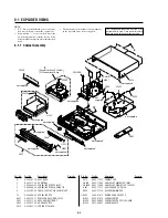
8-1-1 Cabinet Assembly
8-1 EXPLODED VIEWS
NOTE:
•
-XX, -X mean standardized parts, so they may
have some differences from the original one.
•
Items marked “*” are not stocked since they
are seldom required for routine service. Some
delay should be anticipated when ordering these
items.
•
The mechanical parts with no reference number
in the exploded views are not supplied.
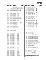
Ref. No.
Part No.
Description
Remarks
Ref. No.
Part No.
Description
Remarks
2
9-885-101-19 ASSY DECK
3
9-885-111-30 DOOR TRAY
7
9-885-069-88 SCREW-TAPTITE ZPC (WHT)
8
9-885-069-84 SCREW-TAPTITE BLK SWCH101
9
9-885-102-43 CABLE-FLAT;30V, 80C, 360MM, 40P
12
9-885-084-32 SCREW-TAPTITE
A001
9-885-112-11 REMOCON ASSY; RDR-VX555
C001
9-885-111-28 ASSY, CABINET FRONT
C003
9-885-111-29 DOOR CASSETTE
C012
9-885-037-13 SPRING ETC MASK
C015
9-885-111-27 CABINET TOP
CN01B
9-885-112-93 CABLE-FLAT; 80MM, 30P, 1MM
*
CNJ02B 9-885-112-94 CABLE-FLAT; 200MM, 14P, 1.25MM
H001
9-885-111-31 ASSY LOADER; TS-P632A
P022
9-885-111-36 ASSY PWB MAIN DVD
0
P025
1-824-674-11 POWER CORD EP2 SPT-2
W001
9-885-079-18 SCREW-TAPTITE
W202
9-885-069-85 SCREW-TAPTITE ZPC (YEL) SWR
W252
3-075-262-01 SCREW BH 4X12
C015
not supplied
not supplied
not supplied
not supplied
not supplied
not supplied
not supplied
not supplied
not supplied
not supplied
not supplied
W202
C003
C012
W001
W001
W001
CNJ02B
CN01B
P025
A001
P022
W252
W202
H001
not
supplied
9
8
3
7
12
C001
2
( )
Except for Assy Cylinder,
H/Cleaner lever Assy
The components identified by mark
0
or
dotted line with mark
0
are critical for safety.
Replace only with part number specified.
Summary of Contents for RDR VX555 - DVDr/ VCR Combo
Page 62: ...2 22 2 22E MEMO ...
Page 64: ...3 4E MEMO ...
Page 66: ...4 1 DVD Main PCB 4 4 4 3 COMPONENT SIDE ...
Page 67: ...4 6 4 5 CONDUCTOR SIDE ...
Page 68: ...4 8 4 7 4 2 VCR Main PCB COMPONENT SIDE ...
Page 69: ...4 10 4 9 CONDUCTOR SIDE ...
Page 70: ...4 12 4 11 4 3 Function PCB COMPONENT SIDE COMPONENT SIDE ...
Page 71: ...4 14 4 13 4 4 Front Jack PCB COMPONENT SIDE CONDUCTOR SIDE ...
Page 72: ...4 16E 4 15 4 5 DV Jack PCB COMPONENT SIDE COMPONENT SIDE ...
Page 74: ...5 4 5 3 5 1 S M P S VCR Main PCB ...
Page 75: ...5 6 5 5 5 2 Power VCR Main PCB ...
Page 76: ...5 8 5 7 5 3 Logic VCR Main PCB ...
Page 77: ...5 10 5 9 5 4 A V VCR Main PCB ...
Page 78: ...5 12 5 11 5 5 Hi Fi VCR Main PCB ...
Page 79: ...5 14 5 13 5 6 MPEG Decoder DVD Main PCB ...
Page 80: ...5 16 5 15 5 7 A V Decoder DVD Main PCB ...
Page 81: ...5 18 5 17 5 8 In Out DVD Main PCB ...
Page 82: ...5 20 5 19 5 9 DV HDMI DVD Main PCB ...
Page 83: ...5 22 5 21 5 10 Front Timer Front Jack PCB DV Jack DV Jack PCB ...
Page 84: ...5 24E 5 23 5 11 Function Function PCB ...
Page 127: ...MEMO ...


