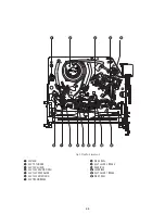


2-19
2
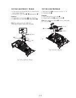
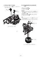
BELT PULLEY
1
HOOK CAPSTAN
HOOK
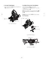
2-4-25 Hook Capstan, Belt Pulley Removal
1) Remove the Hook Capstan
1
after realeasing Hook in the
direction arrow as shown in detail drawing.
2) Remove the Belt Pulley
2
.
Note:
Take extreme care not to get grease on Belt Pulley
2
at
assembling or reassembling.
Fig. 2-38 Belt Pulley Removal
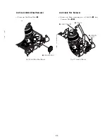
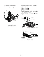
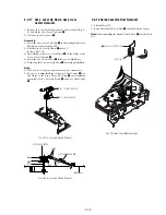
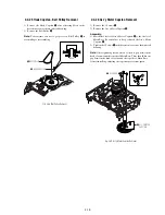
2-4-26 Ass’y Motor Capstan Removal
1) Remove the 3 Screws
1
.
2) Remove the Ass’y Motor Capstan
2
.
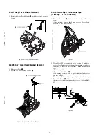
Assembly:
1) Match the 3 holes of Ass’y Motor Capstan
2
to the 3 holes of
Main Base. Be careful not to drop or knock the Ass’y Motor
Capstan
2
.
2) Tighten the 3 Screws
1
in the direction of arrow as shown detail
drawing.
Note:
After tightening screws, check if there is gap between the
head of screws and the top side of Main Base. There should have no
gap between the head of screws and the top side of Main Base.
After reinstalling, adjusting the tape transport system again.
Fig. 2-39 Ass’y Motor Capstan Removal
2
ASS'Y MOTOR
CAPSTAN
1
3 SCREWS
A
B
C
Summary of Contents for RDR VX555 - DVDr/ VCR Combo
Page 62: ...2 22 2 22E MEMO ...
Page 64: ...3 4E MEMO ...
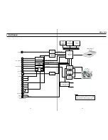
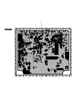
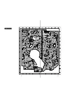
Page 66: ...4 1 DVD Main PCB 4 4 4 3 COMPONENT SIDE ...
Page 67: ...4 6 4 5 CONDUCTOR SIDE ...
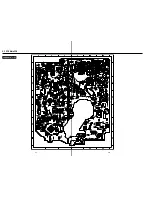
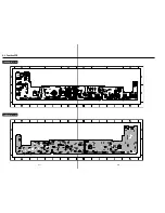
Page 68: ...4 8 4 7 4 2 VCR Main PCB COMPONENT SIDE ...
Page 69: ...4 10 4 9 CONDUCTOR SIDE ...
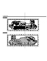
Page 70: ...4 12 4 11 4 3 Function PCB COMPONENT SIDE COMPONENT SIDE ...
Page 71: ...4 14 4 13 4 4 Front Jack PCB COMPONENT SIDE CONDUCTOR SIDE ...
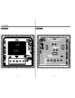
Page 72: ...4 16E 4 15 4 5 DV Jack PCB COMPONENT SIDE COMPONENT SIDE ...
Page 74: ...5 4 5 3 5 1 S M P S VCR Main PCB ...
Page 75: ...5 6 5 5 5 2 Power VCR Main PCB ...
Page 76: ...5 8 5 7 5 3 Logic VCR Main PCB ...
Page 77: ...5 10 5 9 5 4 A V VCR Main PCB ...
Page 78: ...5 12 5 11 5 5 Hi Fi VCR Main PCB ...
Page 79: ...5 14 5 13 5 6 MPEG Decoder DVD Main PCB ...
Page 80: ...5 16 5 15 5 7 A V Decoder DVD Main PCB ...
Page 81: ...5 18 5 17 5 8 In Out DVD Main PCB ...
Page 82: ...5 20 5 19 5 9 DV HDMI DVD Main PCB ...
Page 83: ...5 22 5 21 5 10 Front Timer Front Jack PCB DV Jack DV Jack PCB ...
Page 84: ...5 24E 5 23 5 11 Function Function PCB ...
Page 127: ...MEMO ...


