


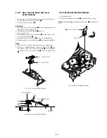
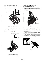
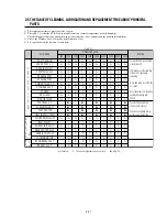


2-16
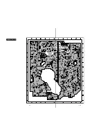
"A"
"B"
2
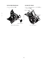
ASS'Y LEVER #9 GUIDE
1
SPRING #9 GUIDE
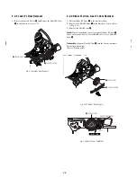
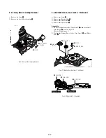
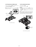
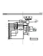
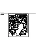
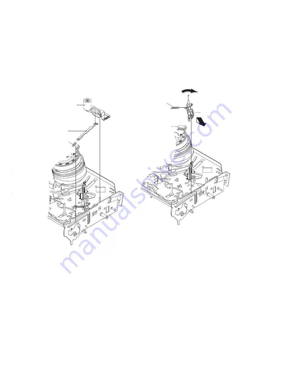
2-4-19 Ass’y Lever Unit Pinch, Plate Joint,
Spring Pinch Drive Removal
1) Lift the Ass’y Lever Unit Pinch
1
.
2) Remove the Plate Joint
2
from Lever Pinch Drive.
3) Remove the Spring Pinch Drive
3
.
Note:
1) Take extreme care not to touch the grease on the Roller Pinch.
2) When reinstalling, be sure to apply grease on the post pinch
roller.
Fig. 2-32 Ass’y Lever Unit Pinch, Plate Joint,
Spring Pinch Drive Removal
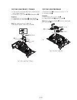
2-4-20 Ass’y Lever #9 Guide Removal
1) Remove the Spring #9 Guide
1
.
2) Lift the Ass’y Lever #9 Guide
2
in the direction of arrow “A”.
Note:
1) Take extreme care not to get grease on the tape Guide Post.
2) After reinstalling, check the bottom side of the Post #9 Guide to
the top side of Main Base.
Fig. 2-33 Ass’y Lever #9 Guide Removal
1
ASS'Y LEVER
UNIT PINCH
2
PLA TE JOINT
3
SPRING PINCH
DRIVE
Summary of Contents for RDR VX555 - DVDr/ VCR Combo
Page 62: ...2 22 2 22E MEMO ...
Page 64: ...3 4E MEMO ...
Page 66: ...4 1 DVD Main PCB 4 4 4 3 COMPONENT SIDE ...
Page 67: ...4 6 4 5 CONDUCTOR SIDE ...
Page 68: ...4 8 4 7 4 2 VCR Main PCB COMPONENT SIDE ...
Page 69: ...4 10 4 9 CONDUCTOR SIDE ...
Page 70: ...4 12 4 11 4 3 Function PCB COMPONENT SIDE COMPONENT SIDE ...
Page 71: ...4 14 4 13 4 4 Front Jack PCB COMPONENT SIDE CONDUCTOR SIDE ...
Page 72: ...4 16E 4 15 4 5 DV Jack PCB COMPONENT SIDE COMPONENT SIDE ...
Page 74: ...5 4 5 3 5 1 S M P S VCR Main PCB ...
Page 75: ...5 6 5 5 5 2 Power VCR Main PCB ...
Page 76: ...5 8 5 7 5 3 Logic VCR Main PCB ...
Page 77: ...5 10 5 9 5 4 A V VCR Main PCB ...
Page 78: ...5 12 5 11 5 5 Hi Fi VCR Main PCB ...
Page 79: ...5 14 5 13 5 6 MPEG Decoder DVD Main PCB ...
Page 80: ...5 16 5 15 5 7 A V Decoder DVD Main PCB ...
Page 81: ...5 18 5 17 5 8 In Out DVD Main PCB ...
Page 82: ...5 20 5 19 5 9 DV HDMI DVD Main PCB ...
Page 83: ...5 22 5 21 5 10 Front Timer Front Jack PCB DV Jack DV Jack PCB ...
Page 84: ...5 24E 5 23 5 11 Function Function PCB ...
Page 127: ...MEMO ...


