


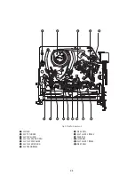


2-7
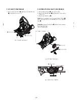
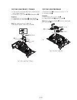
2-4 VCR DECK
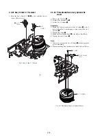
2-4-1 Ass’y Holder Cassette Removal
1) Pull the Ass’y Holder Cassette
1
to the eject position.
2) Pull the Ass’y Holder Cassette
1
as grasping the Ass’y Holder
Cassette
1
and Lever Lock
2
in the same time to release hooking
from Main Base until the Boss [A] of Ass’y Holder Cassette
1
is taken out from the Rail [B].
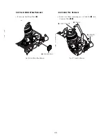
3) Lift the Ass’y Holder Cassette
1
, in this time, you have to grasp
the Lever Lock
2
Continuously until the Ass’y Holder Cassette
1
is taken out completely.
Note:
Be sure to insert Lever Lock
2
in the direction of “A” to
prevent separation and breakage of the Lever Lock
2
at
disassembling and reassembling.
Fig. 2-11 Ass’y Holder Cassette Removal
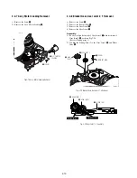
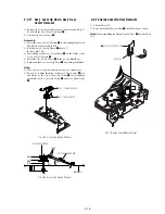
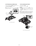
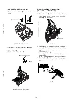
2-4-2 Ass’y Lever Arm Removal
1) Push the hole “A” in the direction of arrow “B” use the pin.(about
Dia. 2.5)
2) Pull out the Ass’y Lever Arm
1
from the Boss of Main Base.
3) Remove the Ass’y Lever Arm
1
in the direction of arrow “C”.
Fig. 2-12 Ass’y Lever Arm Removal
"A"
1
ASS'Y HOLDER
CASSETTEE
BOSS [A]
2
LEVER LOCK
RAIL [B]
PIN
HOLE "A"
1
ASS'Y LEVER ARM
"C"
"B"
Summary of Contents for RDR VX555 - DVDr/ VCR Combo
Page 62: ...2 22 2 22E MEMO ...
Page 64: ...3 4E MEMO ...
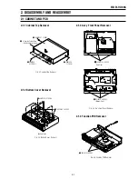
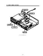
Page 66: ...4 1 DVD Main PCB 4 4 4 3 COMPONENT SIDE ...
Page 67: ...4 6 4 5 CONDUCTOR SIDE ...
Page 68: ...4 8 4 7 4 2 VCR Main PCB COMPONENT SIDE ...
Page 69: ...4 10 4 9 CONDUCTOR SIDE ...
Page 70: ...4 12 4 11 4 3 Function PCB COMPONENT SIDE COMPONENT SIDE ...
Page 71: ...4 14 4 13 4 4 Front Jack PCB COMPONENT SIDE CONDUCTOR SIDE ...
Page 72: ...4 16E 4 15 4 5 DV Jack PCB COMPONENT SIDE COMPONENT SIDE ...
Page 74: ...5 4 5 3 5 1 S M P S VCR Main PCB ...
Page 75: ...5 6 5 5 5 2 Power VCR Main PCB ...
Page 76: ...5 8 5 7 5 3 Logic VCR Main PCB ...
Page 77: ...5 10 5 9 5 4 A V VCR Main PCB ...
Page 78: ...5 12 5 11 5 5 Hi Fi VCR Main PCB ...
Page 79: ...5 14 5 13 5 6 MPEG Decoder DVD Main PCB ...
Page 80: ...5 16 5 15 5 7 A V Decoder DVD Main PCB ...
Page 81: ...5 18 5 17 5 8 In Out DVD Main PCB ...
Page 82: ...5 20 5 19 5 9 DV HDMI DVD Main PCB ...
Page 83: ...5 22 5 21 5 10 Front Timer Front Jack PCB DV Jack DV Jack PCB ...
Page 84: ...5 24E 5 23 5 11 Function Function PCB ...
Page 127: ...MEMO ...


