

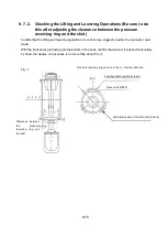


9-7
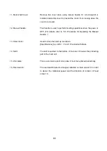
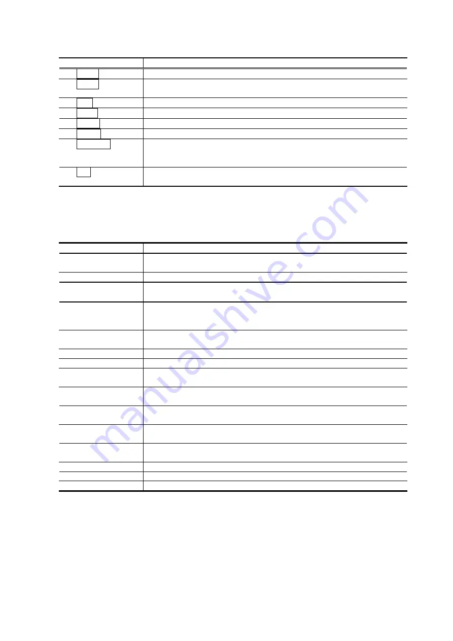
Information LED
Silk name
Function
PRC1
Lights during communication with the processor.
PRC2
Lights during communication with the processor. (2-wave system
only)
STB
Lights when set in a system that uses an inclinometer.
HALF
Lights when set to a half scanning sonar system.
HAND
Lights when the manual handle for maintenance is used.
MANU
Lights in the manual mode.
CENTER
Lights when set in a half scanning sonar system, and also when the
transducer is facing the starboard side from the bow (when the
BEARING is between 0 (hex) and F8 (hex)).
X-Y
Condition in which the inclination values (ROLL and PITCH) are
displayed on the 7-segment LED.
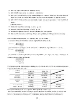
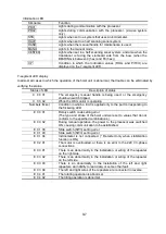
7-segment LED display
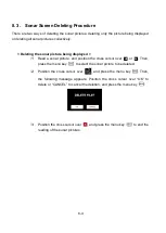
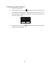
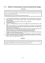
In almost all cases in which the operation of the hoist unit is abnormal, the trouble can be eliminated by
verifying the status.
Status of LED
Description of status
C
00
01
The emergency manual handle is being used, or the emergency
shutdown switch tripped.
C
00
02
While the OK monitor is operating
Numbers flicker
Condition in which a limit is applied only to the part corresponding to
the flickering LED
E
00
01
Rotary switch code setting error
(The type and stroke of the hoist unit were set to values that do not
conform to the specified combinations.)
E
00
02
During manual operation, the power to the processor was switched
ON, causing communication to be established.
E
01
00
Slide switch (SW3) setting error
E
01
03
Slide switch (SW3) setting error
E
01
04
Inclinometer is not connected. (* Detected only when stabilization
function is ON.)
E
02
01
The motor is overloaded, or there is an error in the 220 V 3-phase
connections.
E
03
01
There is an abnormality in the installation or wiring of the repeater
on the right side.
E
03
02
There is an abnormality in the installation or wiring of the repeater
on the left side.
E
03
03
There is an abnormality in the installation of the left and right
repeaters, an inability to read data, or some other fault.
E
03
04
The left and right wires of the repeaters are connected in reverse.
E
04
01
The rotating operation is abnormal.
E
04
02
The tilting operation is abnormal.
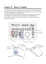
Summary of Contents for KCS-5200
Page 1: ...Model KCS 5200 Color Scanning Sonar Operation Manual Ver 1 48 E Rev 0...
Page 2: ......
Page 14: ......
Page 22: ...2 4...
Page 28: ...3 6...
Page 50: ...5 16...
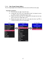
Page 78: ...6 28 Menu Screen Sub Screen Orthogonal Display Axis...
Page 80: ...6 30...
Page 84: ...7 4...
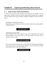
Page 90: ...8 6...
Page 106: ...9 16...
Page 116: ...10 10...


