9-13
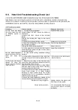
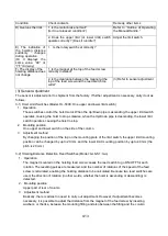
Condition
Check contents
Remedy, other items
D) Overuns the limit.
1. Is the motor brake normal?
(Is it in a released condition?)
Refer to “Outline of Operating
the Manual Handle.”
2. Does the upper limit (or lower limit) switch
operate correctly? (Does it run idle?)
Adjust the limit switch.
E) The indication of
the hoisting distance
suddenly
changes
during operation.
(Or it displays the
same value: “00” or
“7F” mid way)
1. Is the rotary switch set correctly?
F) The display of the
hoisting distance does
not change.
1. Is the magnet at the top of the feed screw
correctly installed?
2. Is the clearance between the magnet at the
top of the feed screw and the reed switch too
wide?
(3) Refer to sensor adjustment.
(3) Sensor Adjustment
The sensor is adjusted prior to shipment from the factory. If further adjustment is necessary, carry it out as
follows.
3-1) Hoist Limit Switches (Model: HL-5000: One upper and lower limit switch)
1. Operation
These switches control the hoist motor. When the Up/Down pipe is ascending, the upper limit switch
operates, causing the hoist to stop. Likewise, when the Up/Down pipe is descending, the lower limit
switch operates, causing the hoist to stop.
2. Mounting position
One upper and lower switch on the side of the column
3. Adjustment method
By changing the position of the tap on the mounting plate of the limit switch, the upper limit mounting
position can be changed by up to 20 mm, and the lower limit mounting position by up to 40 mm (the
pitch is 20 mm).
3-2) Hoisting Distance Detection Reed Switches (Model: GLS-S1: two)
1. Operation
The magnet mounted on the hoisting feed screw causes the reed switch to go ON/OFF for each
rotation. The resulting pulses are measured, and the number of rotations of the speed of the feed
screw is calculated, enabling the hoisting distance to be calculated. Because two reed switches are
used, the direction of rotation (in other words, whether the hoist is ascending or descending) is
detected.
2. Mounting position
Upper part of rear of column
3. Adjustment method
Basically, there is almost no need to carry out adjustment. However, if adjustment becomes
necessary, it is possible to adjust the distance from the magnet of the feed screw by inserting
washers, or the like, between the mounting fitting and also between the fitting and the column.
Summary of Contents for KCS-5200
Page 1: ...Model KCS 5200 Color Scanning Sonar Operation Manual Ver 1 48 E Rev 0...
Page 2: ......
Page 14: ......
Page 22: ...2 4...
Page 28: ...3 6...
Page 50: ...5 16...
Page 78: ...6 28 Menu Screen Sub Screen Orthogonal Display Axis...
Page 80: ...6 30...
Page 84: ...7 4...
Page 90: ...8 6...
Page 106: ...9 16...
Page 116: ...10 10...


