9-2
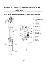
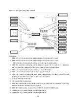
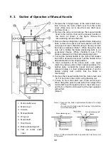
1. Relay box:
This box houses electrical components and also the control board.
(Refer to “9.2. Relay Box”.)
2. Emergency shutdown button:
If the emergency shutdown button is pressed during AUTO operation,
the hoist will stop. To resume the lifting or lowering operation, press
the UP or DOWN switch of the indicator once again. If the emergency
shutdown button is pressed during a MANU operation while the UP or
DOWN button remains pressed, the hoist will remain stopped as long
as the switch is pressed, but will continue to move as soon as the
switch is released, so be careful. If the emergency shutdown switch is
pressed during a hoisting operation, the hoisting operation will stop.
(For de
tails, refer to “9.2. Relay Box.”)
3. Cable gland:
Used to fix the oscillator cable by retaining it at the exit of the
UP/Down pipe, and packing it.
4. Junction box:
Uses connectors for connecting the oscillator cable to the cable on
the transducer side, and houses them.
5. Cable fixing piece:
A component to fix the cable from the transducer side.
6. Limit switches:
These switches are for the upper limit and lower limit of the hoisting
operation. When these switches are ON, the hoist will stop at the
respective limit positions.
7. Guide ring:
Reduces the traveling resistance and also the load applied to the
UP/Down pipe when the oscillator is thrust out.
8. Dome :
Contains an oscillator.
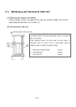
9. Gland retainer:
Uses four bolts (M12) to retain the gland packing and maintain water
resistance.
10. Feed screw:
This screw converts the rotation of the hoist motor 13 into linear
motion (hoisting motion).
Summary of Contents for KCS-5200
Page 1: ...Model KCS 5200 Color Scanning Sonar Operation Manual Ver 1 48 E Rev 0...
Page 2: ......
Page 14: ......
Page 22: ...2 4...
Page 28: ...3 6...
Page 50: ...5 16...
Page 78: ...6 28 Menu Screen Sub Screen Orthogonal Display Axis...
Page 80: ...6 30...
Page 84: ...7 4...
Page 90: ...8 6...
Page 106: ...9 16...
Page 116: ...10 10...


