- 27 -
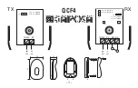
(3) Controller parts description
No.
Display
Description
Details
1 PWR
Power
supply/Alarm
LED (Green)
Normal operation: Green
However, if also the ALM LED is lit or flashes, an error has been
generated.
2
ALM
Alarm LED (Red)
In alarm condition: Lit or flashes
The combination of lit or flashing ALM and PWR LED’s indicates
the content of an alarm.
3 CN5
Parallel I/O
connector
(20 pins)
Connection to a PLC via the LATH2-
∗
I/O cable.
(6 inputs, common (COM) terminal for the input signals, 4
outputs, positive and negative power supply terminals for the
output signals)
4 CN4
Counter
connector
(5 pins)
Connection to the CEU5 multi-counter via the LATH3-
∗
counter
cable.
5 CN3
Serial I/O
connector
(9 pins)
Connection to a PC via the controller setting cable.
6 CN2
Motor connector
(18 pins)
Connection to the Card Motor via the LATH1-
∗
actuator cable.
7 CN1
Power supply
connector
(2 pins)
24 VDC power supply connection to the controller using the
power supply plug and a power supply cable.
8
―
Controller part
number label
Label indicating the part number of the controller.
9
―
FG
Frame ground
(When the controller is mounted, tighten screws and connect the
grounding cable.)
(3)
(5)
(6)
(7)
(9)
(8)
(1)
(2)
(4)