background image

- 49 - 


(1) Operate within the limits of the maximum usable stroke. 

The stopper will be damaged if the Card Motor is used with a stroke outside the maximum stroke 
limits. Refer to the Card Motor specifications for maximum strokes. 
 

(2) Do not apply a load outside the specifications. 

The Card Motor should be fitted for the application based on the maximum workload and allowable 
moments. If the product is used outside the specifications, the excess load applied to the guide will 
lead to play in the guide, decrease in accuracy and the life span of the product will be shortened. 


(3) When the product is repeatedly cycled with short strokes, operate it at a full stroke at least 

once every 10 strokes. 

Otherwise, the parts of guides where it is being used may run out of lubrication. 


(4) In pushing operation use thrust force setting values within the allowable limits based on the 

used duty ratio. 

If thrust force setting values outside the allowable limits are used, it may cause overheating of the 
Card Motor, the work piece or the mounting surface. 


(5) Strong magnet 

The Card Motor contains a strong rare-earth magnet, whose magnetic field may affect the work 
piece. Mount the work piece away from the Card Motor far enough to prevent the magnetic field 
from affecting the work piece. 


(6) Do not use the product in applications where impact or excessive external force is applied to it. 

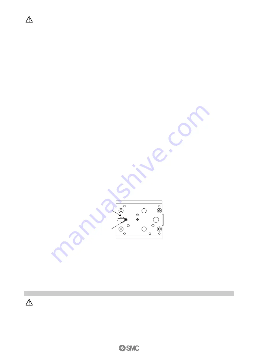
The Card Motor is equipped with a stopper to prevent the table from coming off and to be resistant to 
the light impacts generated when returning to Origin position and when transferring work pieces 
within the spevcified limits. Excessive external force or impact may damage the Card Motor, so 
install a separate external stopper if the operating conditions require. 


(7) It is not possible to perform [Return to Origin Position] during another operation. 

It is not possible to perform [Return to Origin position] during positioning and pushing operation. 

 
(8) The flatness of the mounting surface of the table and rail must be 0.02 mm or less. 

Insufficient flatness of the mounting base for the Card Motor, or of a work piece mounted to it can 
cause play in the guide and an increase in the sliding friction. 


5. 2 Handling Precautions


(1) Do not touch the product when it is energized or for some time after it has been de-energized. 

The surface temperature of the Card Motor can increase up to approximately 70

o

C depending on 

the operating conditions. Energizing alone may also cause the temperature to rise. Do not touch the 
Card Motor during operation or when energized to prevent burns or other injuries. 


Caution 

Warning 

Card Motor rail 

(bottom) 

Stopper 

Summary of Contents for LAT3 Series

Page 1: ...PRODUCT NAME Card Motor Model Series Product Number LAT3 Series Doc No LA OMP0023 A Controller LATC4 Series...

Page 2: ...le 34 3 6 Controller setting kit 34 3 7 Multi counter 35 4 Setting and operation 38 4 1 Step data setting method 38 4 2 Return to Origin position 41 4 3 Positioning operation 43 4 4 Pushing operation...

Page 3: ...6 8 Maintenance 58 7 Common Precautions for wiring and cables 59 8 Alarm detection 60 8 1 Alarm LED display 60 8 2 Alarms and countermeasures 61 9 Troubleshooting 62 9 1 Operation troubles 62 9 2 Pos...

Page 4: ...ty of equipment failure when configuring the equipment 2 Only personnel with appropriate training should operate machinery and equipment The product specified here may become unsafe if handled incorre...

Page 5: ...esponsibility a replacement product or necessary parts will be provided This limited warranty applies only to our product independently and not to any other damage incurred due to the failure of the p...

Page 6: ...d wire for each terminal Twist the wires together and strip the ends as shown The insulation should be rated to withstand 60o C temperature minimum Wiring of the power supply plug Connect the positive...

Page 7: ...er than the specified range may damage the Card Motor Insufficient tightening torque may cause the actuator or the work piece to come loose or position displacement 1 Mounting of the Card Motor from t...

Page 8: ...DF in the Controller Setting Software CD ROM for instructions on how to check the COM port number 100 500 200 1000 50 200 1 2 3 120 3 200 mm mm s 100 500 200 1000 50 200 1 2 3 120 3 200 mm mm s Card M...

Page 9: ...workpiece to a specific position Pushing operation When applying force to a workpiece or measuring the size of it G Select movement mode Absolute The Card Motor table will move the set distance in rel...

Page 10: ...connected Card Motor If they do not correspond the Card Motor will operate at a position speed and thrust different from the settings leading to operation failure Set the approximate value of the work...

Page 11: ...turn to Origin button to move the table to the Origin Position iii Enter the desired Jog Speed iv The table can now be moved at the set speed in either direction by pressing either the Connector Side...

Page 12: ...he set speed If it is necessary to stop the operation press Servo On vi to de energize the Card Motor Warning Consider the operational behavior of the table when the power supply to the motor is turne...

Page 13: ...will not be fixed and can be moved by external force Check that the table movement cannot cause any human injury or damage to the equipment Caution Consider table movements of the Card Motor and exter...

Page 14: ...art the operation E Operation End The operation ends and the motor becomes de energized after the Card Motor has repeated the amount of cycles set in the Repeat Count text box in item C in the figure...

Page 15: ...Servo Off Note The type of the alarm can be detected by checking the combination of lit and flashing ALARM and POWER LED s Refer to section 8 Alarm detection P 60 or the LATC4 series controller operat...

Page 16: ...of the Controller Setting Software Refer to section 1 4 5 Monitor Mode P 19 for details of the Monitor Mode 1 Wiring Switch the power off from the controller and disconnect the controller setting cabl...

Page 17: ...ce 10 k B10 NC B9 NC B8 NC B7 NC B6 OUT1 B5 OUT0 B4 ALARM B3 BUSY B2 DC2 B1 DC2 A10 NC A9 NC A8 NC A7 SVON A6 DRIVE A5 IN3 A4 IN2 A3 IN1 A2 IN0 A1 COM CN5 24 VDC power supply for the input signals The...

Page 18: ...PLC can be checked using the I O status and Manual Output functions A Input signal check Use the PLC to turn ON and OFF the output signals to the IN0 IN1 IN2 IN3 DRIVE and SVON controller inputs and...

Page 19: ...n cleared Note The type of the alarm can be detected by checking the combination of lit and flashing ALARM and POWER LED s Refer to section 8 Alarm detection P 60 or the LATC4 series controller operat...

Page 20: ...operation commands sent from the PLC to the controller via the parallel I O Warning All the limitations are cancelled by switching between Test Mode and Monitor Mode The power supply to the Card Moto...

Page 21: ...33 Note 2 The DIN rail is not included If the DIN rail is required please order separately Refer to the LAT3 series catalogue for details Card Motor Sensor resolution NIL 30 m F 1 25 m I O cable leng...

Page 22: ...tructions regarding wiring and handling of cables Complete the Controller setting cable assembly by connecting the USB cable to the Conversion unit attached at the end of the Communication cable Note...

Page 23: ...g temperature range o C 5 to 40 No condensation Operating humidity range 35 to 85 No condensation Weight g Note 7 130 190 250 Table weight g 50 70 90 Note 1 Continuous thrust can be generated and main...

Page 24: ...Thrust setting value 3 Thrust setting value 5 0 1 2 3 4 5 6 0 5 10 15 20 Thrust force N Pushing position mm Thrust setting value 1 Thrust setting value 2 8 Thrust setting value 4 8 0 1 2 3 4 5 6 0 5...

Page 25: ...r the distances to the moment centre LAT3 10 22 5mm LAT3 20 32 5mm LAT3 30 42 5mm 0 00 0 01 0 02 0 03 0 04 0 05 0 2 4 6 Load N Table displacement mm 0 00 0 01 0 02 0 03 0 04 0 05 0 2 4 6 Load N Table...

Page 26: ...Note 1 Refer to Mounting screw specifications and tightening torques in section 1 1 Preparation P 5 Note 2 The length of the part of the dowel pin inserted into the positioning hole should be shorter...

Page 27: ...ensation Ambient humidity range 35 to 85 No condensation Insulation resistance 50 M 500 VDC between the case and the FG terminal Weight Note 4 130g Screw mounting type 150g DIN rail mounting type Comp...

Page 28: ...puts positive and negative power supply terminals for the output signals 4 CN4 Counter connector 5 pins Connection to the CEU5 multi counter via the LATH3 counter cable 5 CN3 Serial I O connector 9 pi...

Page 29: ...28 4 Controller Screw mounting type LATC4 DIN rail mounting type LATC4 D...

Page 30: ...g the CEU5 Multi counter to the controller counter connector Note Refer to section 3 7 Multi counter P 35 for Multi counter wiring and setting instructions Caution Do not connect multiple wires to one...

Page 31: ...B10 NC B9 NC B8 NC B7 NC B6 OUT1 B5 OUT0 B4 ALARM B3 BUSY B2 DC2 B1 DC2 A10 NC A9 NC A8 NC A7 SVON A6 DRIVE A5 IN3 A4 IN2 A3 IN1 A2 IN0 A1 COM CN5 24 VDC power supply for the input signals The power...

Page 32: ...O connector There are two types of parallel inputs and outputs for this controller NPN type LATC4 N and PNP type LATC4 P Please confirm the specification before wiring The 24 VDC power supply for the...

Page 33: ...eration both when moving and when held in position The Threshold Force Value can be set in the I O Setup tab in the Controller Setting Software Caution The Threshold Force Value is set in the I O Setu...

Page 34: ...AWG size 28 AWG Terminal number Function B1 DC2 B2 DC2 B3 BUSY B4 ALARM B5 OUT 0 B6 OUT 1 B7 NC B8 NC B9 NC B10 NC Note The actuator cable is direction dependent Connect the Card Motor side of the ca...

Page 35: ...USB cable 3 Hardware and operating system requirements PC with WindowsXP or Windows7 and USB1 1 or USB2 0 port Windows WindowsXP and Windows7 are registered trademarks of the United States Microsoft C...

Page 36: ...n setting mode Display type LCD with back light Number of digits 6 digits Counting speed 100 kHz Insulation resistance Between case and AC line 500 VDC 50 M or more Ambient temperature 0 to 50o C No f...

Page 37: ...ame Insulation colour LATC4 controller A Red Insulation colour Name COM Black White PhaseB B White Red PhaseA COM Blue Light gray GND DC12V Yellow RESET GND Green F G F G Green RESET Yellow HOLD COM B...

Page 38: ...l end stop If another position defined by stopping the table against an external mechanical stop is used to display the zero position in the Multi counter use a PLC or a similar device capable of outp...

Page 39: ...peed trapezoidal movement profile The table moves to the set position based on the set speed acceleration and deceleration 1 Cycle time entry method Setting items Target position mm Positioning time s...

Page 40: ...istance Sa 0 5 X Aa X Ta2 mm Deceleration distance Sd 0 5 X Ad X Td2 mm Travel distance with constant velocity Sc S Sa Sd mm Travel time with constant velocity Tc Sc Vc s Positioning time Tp Ta Tc Td...

Page 41: ...rforms the pushing operation with the set Thrust Setting Value in the pushing direction from the current position Caution In relative positioning the deviation will remain Therefore the table destinat...

Page 42: ...stops at the Origin position 0 The return to Origin position method is set to Retracted End Position in the initial condition Extended End Position The table moves towards the opposite side of the co...

Page 43: ...nce example The controller uses the Load Mass value set in Step Data No 1 for the Return to Origin operation Therefore confirm that the Load Mass value for Step Data No 1 is appropriate for the Return...

Page 44: ...The table moves based on the set acceleration speed and deceleration according to a trapezoidal movement profile 3 and stops at the set target position 4 1 3 Moves at high speed 2 4 Target position T...

Page 45: ...When the table travels at a maximum speed of 6 mm s or less before it has started pushing 1 4 the pushing speed 2 5 will be the same as the maximum travelled speed 1 4 Allowable thrust force setting...

Page 46: ...damage the Card Motor Install a separate external stopper if the operating conditions require For pushing operations set the target position at least 1 mm away from the position where the table or the...

Page 47: ...git display the decimal numbers will not be displayed when the resolution is set to 1 25 Caution The Multi counter may lose pulses when a long counter cable is used or the Card Motor travels at high s...

Page 48: ...to output up to 31 preset positions using the CEU5 Multi counter Good Bad Judgement and Differentiation of workpieces Good Bad judgment ON OFF Time AREA A signal Tolerance Table position Judgement re...

Page 49: ...o that they will not come loose When the Card Motor operates with high frequency or is installed where there is a lot of vibration ensure that all parts remain secure 5 Consider the possibility of pow...

Page 50: ...gh to prevent the magnetic field from affecting the work piece 6 Do not use the product in applications where impact or excessive external force is applied to it The Card Motor is equipped with a stop...

Page 51: ...the work other than those working with the products 3 Strong magnet The Card Motor contains a strong rare earth magnet If a magnetic card is brought close to the Card Motor the card data may get dist...

Page 52: ...the product Also keep this manual available whenever necessary 2 Strong magnet The Card Motor contains a strong rare earth magnet If magnetized work pieces tools and metallic parts are brought in the...

Page 53: ...crew in depth is exceeded it may damage the internal components Using a tightening torque higher than the specified torque may cause malfunction and using a lower tightening torque may displace the wo...

Page 54: ...ources such as direct sunlight The Card Motor uses an optical sensor to detect the position so if it is exposed to a strong light source such as direct sunlight a malfunction could result In such a ca...

Page 55: ...inspection 6 Controller and Peripheral Devices Specific Product Precautions 6 1 Design Selection 1 Use the specified voltage If the applied voltage is higher than the specified voltage malfunction and...

Page 56: ...and for some time after the power has been disconnected as it is very hot It may cause burns due to the high temperature 8 Before performing installation wiring and maintenance check for accumulated...

Page 57: ...on can result 3 Do not mount the controller and its peripheral devices on the same base together with a large sized electromagnetic contactor or no fuse breaker that generate vibration Mount them on d...

Page 58: ...00 or less 3 The grounding point should be as close as possible to the controller and the ground wires as short as possible 4 In the unlikely event that malfunction may be caused by the ground it may...

Page 59: ...ion or damage to the internal circuits of the products Avoid supplies of surge generation and crossed power and signal lines 7 The Card Motor and the controller are not immune to lightning strikes 8 D...

Page 60: ...the cables together with power or high voltage cables It can cause malfunction to the product due to noise and surge voltage interference from power and high voltage cables to the signal line Route t...

Page 61: ...erring to section 8 2 Alarms and countermeasures P 61 Alarms are divided into two types One can be cleared by resetting ON OFF ON the SVON input signal The other can only be cleared by switching off t...

Page 62: ...ed causing an overcurrent to flow through the Card Motor and when overcurrent flows through the parallel output terminals Check if the conditions described below occur 1 The motor cannot reach the tar...

Page 63: ...or wiring Example P 28 Alarm generated Controller alarm is generated Refer to the operation manual of the controller Check the type of alarm Refer to the operation manual of the controller and take ap...

Page 64: ...lay and controller scan delay are generated Please ensure an interval of 2msec or more between input signals and maintain the signal state 9 5 Controller input signal response time P 41 Operation stop...

Page 65: ...mber with the conversion unit connected to the PC The COM port number can be checked using the Device Manager in the PC For details of the COM port checking and setting methods refer to the LATC W1 Co...

Page 66: ...positioning the table moves the set travel distance from the current table position Therefore ensure that the initial table starting position is where the table is supposed to be before starting relat...

Page 67: ...51 Speed does not reach the desired speed Voltage drop Temporary voltage drop in the power supply Possibility of momentary voltage drop due to an inadequate power supply capacity is inadequate or the...

Page 68: ...14 1 Sotokanda Chiyoda ku Tokyo 101 0021 JAPAN Tel 81 3 5207 8249 Fax 81 3 5298 5362 URL http www smcworld com Note Specifications are subject to change without prior notice and any obligation on the...

Reviews: