


- 57 -
No.JXC
※
-OMV0005-A
14.3 Operation procedure for Operation by numerical instruction
E.g.) Input 50.00 [mm] to the position parameter of the specified step data and start the actuator.
Turn ON “RUN (Start flag)” after 12 items are specified (same as the items of the step data).
•Movement mode, speed, target position, acceleration / deceleration, pushing force, trigger LV,
In-position.
Specified by process data Byte2-15.
All of the 8 items above must be numerically instructed for every numerically instructed
operation.
•Positioning force, pushing force, area 1 /2.
These are registered to the step data in advance. The step data is instructed using IN0-IN5 for
numerically instructed operation.
- Procedure -
"Output" and "Input" in the
procedure indicates the
following.
Output
:
Process data output
Input
:
Process data input
(1) Confirm that
“Output,byte0,bit0:
“Run” = OFF.
Turn OFF “Run”, when it is ON.
(2) Specify the step data number
for positioning force, pushing
speed, area 1, and area 2 using
output Byte0,bit0-5:IN0-5.
E.g.) Specify step data No.1
→Turn ON the
“Output,byte0,bit0:IN0” ,
Turn OFF the
“Output,byte0,bit1-5: IN1-5”.
This is the step data that the
positioning force, the pushing
force, and Area1/2 are used.
(3)
Set “Output,byte2-15” as
numerical operation data.
(8 items must be set
numerically)
(4) Turn ON the
“Output,byte0,bit0: Run”.
The actuator starts operating
based on numerically
instructed values.
(5) When the actuator starts and input Byte1, Bit0:BUSY=ON is output, the output Byte0,Bit7:RUN
flag=OFF is input.
(6) When the actuator moves to the target position, "Input,byte1,bit3:INP" is ON.
When the actuator stops, Input,byte1,bit0:BUSY is OFF.
When both
”Input,byte1,bit3:INP”=ON and ”Input,byte1,bit0:BUSY”=OFF are established, the
specified operation is considered to be completed.
Before a numerically instructed operation starts,
confirm it is a state of “SVRE=1 (The servo motor is
ON)” and “SETON=1 (The returning to origin is completed)”.
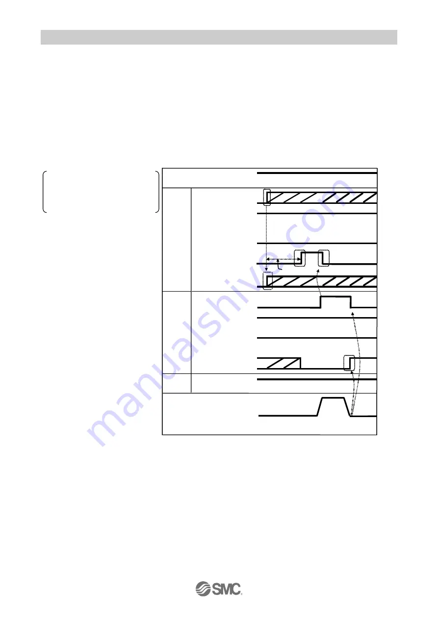
- Timing chart / numerically instructed operation -
(DRIVE signal is not used)
OFF
Power supply
INP
SETON
DRIVE
External lock
Status
signals
Control
signals
IN0 to 5
SVON
Start flag
Numerical
operation data
BUSY
SVRE
Speed
24V
0V
Unlock
Held
ON
OFF
ON
OFF
0mm/s
(1)
(2)
(3)
(5)
(6)
(4)
ON
-
-
-
-
-
-
-
-
-
-
-
-
-
More than twice the communication
cycle time