Start-up procedures
91
851-164336 / D
4
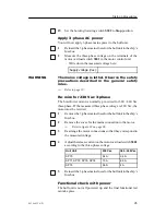
Measure the mains voltage supplied to the Transceiver Unit.
- Write down the measured voltage here:
Supply voltage (Vac):
5
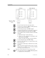
Check that the voltage selector switches,
S201
on the power
supply and
S203
on the HV power unit, correspond to the
measured voltage (115 Vac or 230 Vac position).
6
Reinsert the mains input connector
P201
on the front of the
power supply.
7
Check that lamps
L201
and
L202
on the front of the power
supply illuminate.
8
Check that the small LED (Light Emitting Diode) for the
+24 Vdc stand-by power on the Transceiver Interface Board
(TIB) illuminates.
- Refer to the indicator on the front of the power supply.
The +24 Vdc stand-by power is now supplied both to the Hull Unit
and to the connector for the Sonar Interface Unit.
Summary of Contents for Simrad SP70
Page 2: ......
Page 14: ...Simrad SP70 X 851 164336 D This page is intentionally left blank...
Page 62: ...Simrad SP70 46 851 164336 D Figure 13 Mounting the Transceiver Unit CD3110A...
Page 226: ...Simrad SP70 210 851 164336 D Party Date Signature Party Date Signature Party Date Signature...
Page 227: ......
Page 229: ......


