4-10
ET 200U Distributed I/O Station
EWA 4NEB 812 6087–02b
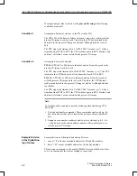
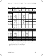
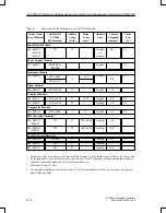
Table 4-1
Address IDs for the Modules in an ET 200U(DP Siemens) Station
Order Num-
ber of Module
Address ID
ET 200U
(DP Siemens)
Address
Scope
(Byte)
Delay
Time
(ms)
1
Address
Area
Current
Consump-
tion (mA)
Power
Loss
(W)
Digital Inputs 6ES5 ...:
420–8MA11
4DI or 008
1
2.5 to 5
Digital
16
0.8
421–8MA12
8DI or 009
1
2.3 to 4.5
Digital
34
1.6
422–8MA11
027
2*
3 to 4
Digital or
analog
50
4.5
430–8MB11
4DI or 008
1
1.4 to 5
Digital
5
2
430–8MC11
4DI or 008
1
10 to 20
Digital
16
2.8
430–8MD11
4DI or 008
1
10 to 20
Digital
16
2.5
431–8MA11
8DI or 009
1
4 to 5.5
Digital
32
2
431–8MC11
8DI or 009
1
10 to 20
Digital
32
2.5
431–8MD11
8DI or 009
1
10 to 20
Digital
32
3.6
433–8MA11
8DI or 009
1
1 to 10
Digital
6
2.4
437–8EA12
4DI or 008
1
40
Digital
50
0.45
Digital Outputs 6ES5 ...:
440–8MA11
048
1
< 1
Digital
15
3
440–8MA21
048
1
< 1
Digital
15
4.8
441–8MA11
8DQ or 017
1
< 1
Digital
14
3.5
450–8MB11
048
1
< 1
Digital
15
5
450–8MD11
4DQ or 016
1
< 1
Digital
14
3.5
451–8MA11
8DQ or 017
1
< 1
Digital
24
4
451–8MD11
8DQ or 017
1
< 1
Digital
25
3.5
451–8MR11
8DQ or 017
1
< 1
Digital
30
1.6
451–8MR12
8DQ or 017
1
< 1
Digital
30
1.6
452–8MR11
4DQ or 016
1
< 1
Digital
14
2
453–8MA11
8DQ or 017
1
< 1
Digital
20
1
457–8EA12
048
1
< 1
Digital
55
0.5
*
The address scope is necessary for the inputs and the outputs (i.e. if the address scope is 2 bytes, 2 bytes are used
for the inputs and 2 bytes are used for the outputs). Since COM ET 200 assigns the addresses for these modules
optionally, inputs and outputs can have different start addresses.
1
For an input module, the delay time is the time between a signal change at an input and a change of state on the I/O
bus. For an output module, the delay time is the time between a signal change on the I/O bus and a change of state
at an output.
ET 200U(DP Siemens): Address Assignment,Starting–Up,Diagnosing Faults Using COM ET200

