5-13
ET 200U Distributed I/O Station
EWA 4NEB 812 6087–02b
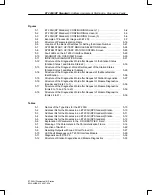
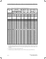
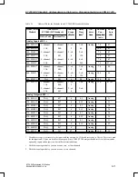
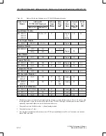
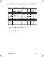
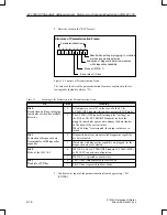
Table 5-5
Address IDs for the Modules in an ET 200U(DP Standard)
Order No. of
Module
Address ID
ET 200U(DP Standard)
Address
Scope
(Byte)
Delay
Time
(ms)
1
Ad-
dress
Area
Current
Con-
sumption
Power
Loss
(W)
Order Code
Decimal No.
(Byte)
(ms)
1
Area
sumption
(mA)
(W)
IP 264 Electronic Cam Controller:
264–8MA11
1
4AX/000
243/000
8*
Analog
120
4
High Speed Sub Control IP 265:
2
265–8MA01
4AX
243
8*
Analog
CP 521 BASIC:
521–8MB11
4AX
243
8*
Analog
180
1.6
CP 521 SI:
521–8MA21
4AX
243
8*
Analog
140
1.2
330–8MA11
or no module
plugged in
000
000
0
0
*
The address scope is necessary for the inputs and the outputs (i.e. if the address scope is 2 bytes, 2 bytes are used
for the inputs and 2 bytes are used for the outputs). Since COM ET200 assigns the addresses for these modules
optionally, inputs and outputs can have different start addresses.
1
The module occupies 2 slots.
2
IP 265 can be operated in Slow Mode only. The Slow Mode must be set in the parameterization frame. Please refer
to Figure KEIN MERKER for the Slow Mode setting.
ET 200U(DP Standard): Address Assignm.,Starting–Up, Diagnosing Faults Using COM ET 200


