


7-26
ET 200U Distributed I/O Station
EWA 4NEB 812 6087–02b
1
2
S+
S–
3
5
7
9
4
6
8
10
S+
S–
QV
M
ANA
QV
M
ANA
L+
M
DC 24 V
QV
(4/8)
S+
(3/7)
M
ANA
(6/10)
S–
(5/9)
R
L
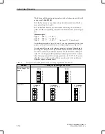
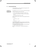
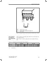
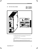
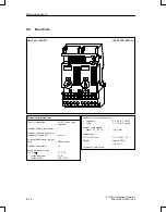
Key:
QV:
Analog Output “Voltage”
S”:
Sensor Line
M
ANA
: Chassis Ground Terminal of the Analog Unit
R
L
:
Load Resistor
Figure 7-9 Load Connection via a Four–Wire Circuit (6ES5 470–8MA11,
6ES5 470–8MD11)
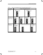
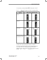
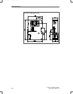
Figure 7-10 shows how to connect loads to the current outputs of the follow-
ing modules:
470–8MB11 (2
20 mA)
and
470–8MC11 (2
+4 to 20 mA)
Analog Value Processing