3-30
ET 200U Distributed I/O Station
EWA 4NEB 812 6087–02b
A configuration in which the control circuit and the load circuit are galvani-
cally isolated is a floating configuration.
A floating configuration is necessary under the following conditions:
When you need to increase interference immunity of load circuits
When you cannot interconnect load circuits
(e.g., because the sensors have different reference voltages, or power is
supplied from batteries, or the positive pole of the battery is grounded)
and
When you are using AC load circuits
A floating configuration can be one of the following two types:
Ungrounded
and
Grounded
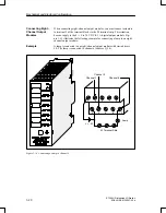
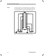
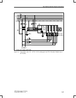
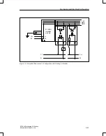
For an ungrounded configuration, you must provide isolation monitoring to
ground with voltage limitation (see Figure 3-20). Do not connect the ground
terminal of the IM 318–B interface module to the grounded standard mount-
ing rail.
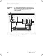
For a grounded configuration, connect the ground terminal of the ET 200U
interface module to the grounded standard mounting rail. When the load cir-
cuit is grounded, the grounding of the ET 200U interface module removes the
galvanic isolation.
A floating configuration has the following characteristics:
Differences in potential do not result in compensating currents. Equipo-
tential bonding conductors are not necessary between the devices (e.g.,
between tiers or stations).
Dangerous contact voltages with respect to ground are possible. Avoid
them through such measures as grounding specific system parts or by us-
ing isolation monitoring with voltage limitation.
Floating Configu-
ration
Mechanical and Electrical Configuration

