3-20
ET 200U Distributed I/O Station
EWA 4NEB 812 6087–02b
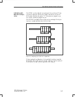
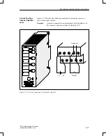
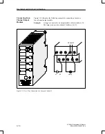
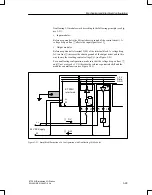
When connecting eight–channel output modules, you must connect actuators
to terminal 2 of the terminal block via the M terminal strip. This situation
does not apply to the 8
5 to 24 V DC/0.1 A digital output module. Fig-
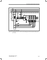
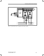
ure 3–15 illustrates the following example for connecting a lamp to an eight–
channel output module:
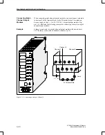
A lamp is connected to an eight–channel output module with start address
5.0. The lamp is connected to channel 6 (address Q 5.6).
1
3
5
7
9
2
4
6
8
10
Channel 6
L+
M
Lamp
Channel 0
Channel 1
M Terminal Strip
Figure 3-16 Connecting a Lamp to Channel 6
Connecting Eight–
Channel Output
Modules
Example
Mechanical and Electrical Configuration

