9-37
ET 200U Distributed I/O Station
EWA 4NEB 812 6087–02b
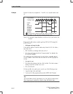
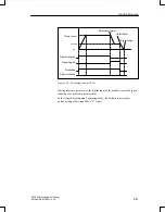
After reaching setpoint 1, output Q0 is energized and status bit S1 is set. Af-
ter reaching setpoint 2, output Q1 is energized and status bit S2 is set.
As long as the enable input is active, the outputs are switchable through the
module. If the enable command is cancelled, the outputs are switched off and
the diagnostics bits are reset. The current actual value is still being measured
and incremented or decremented depending on the direction of rotation.
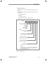
You can read the current count in the STEP 5 program. The actual value is
displayed as a signed whole number in two’s complement and lies in the
range of – 32768 to + 32767.
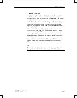
Note
Before you enable the outputs to be switched on by setting the enable input
to 1, make sure the following conditions exist:
The SYNC bit = 1.
The overflow bit = 0.
Both setpoints were transferred.
If you ignore these prerequisites, the outputs are switched on directly
when the actual value = 0.
If the actual value = 0, the outputs are turned on. The diagnostics bit and the
output are reset with the “0” signal at the enable input.
Outputs Q0 and Q1 are also reset when the programmable controller goes
from RUN to STOP.
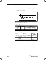
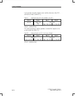
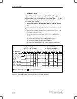
The following examples show the switching on of the output at the selected
setpoint. Following are the three possibilities:
Reaching the setpoint in the direction of a rising actual value
Reaching the setpoint in the direction of a falling actual value
Reaching the setpoint in the direction of a rising actual value, then a re-
versal of direction and a reapproaching of the setpoint in the opposite
direction.
Function Modules


