90/166
Siemens Building Technologies
Basic Documentation RVA47.320
CE1P2379E
HVAC Products
Description of the heating engineer settings
15.07.2002
The contacts of the control thermostat must be suited for extra low voltage (gold-
plated)!
When using a d.h.w. sensor:
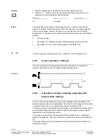
The controller calculates the switching points with the respective switching differential
as a function of the d.h.w. temperature setpoint entered.
Sensor / line with a short-
= fault message
Sensor value available
= d.h.w. according to the current setpoint
Sensor / line with a short-
= no d.h.w.
When using a d.h.w. control thermostat:
The controller takes into consideration the switching statuses of the control thermostat.
Line / terminal with short-circuit = d.h.w. charging ON
Line / terminal with open-circuit = d.h.w charging OFF
Contact resistance too high
= error message from the thermostat
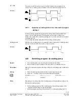
When using a d.h.w. control thermostat, reduced operation is not possible.
•
The nominal d.h.w. temperature setpoint (operating line 13) must be equal to or
higher than the setpoint adjusted on the control thermostat (thermostat is calibrated
at switch-off point)
•
Boost of the flow temperature setpoint (setting on operating line 126) must be
minimum of 10 °C (has an impact on the charging time)
•
In that case, frost protection for d.h.w. is not ensured
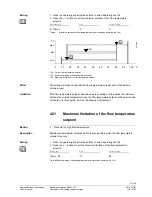
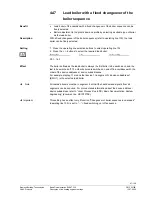
50 °C
56 °C
60 °C
70 °C
SD = 6 °C
∆
T > 0 °C
TBWw
23
71
Z36
TBWw + UEBW
TRw - SD
TRw
UEBW >= 10 °C
UEBW
=
Boost of the temperature setpoint (setting 126)
TBWw
=
Nominal setpoint of the d.h.w. temperature (setting on operating line 13)
TRW - SD
=
setpoint of the thermostat minus the switching differential
TRw
=
setpoint of the thermostat
(point of calibration)
4.42
Boost of the flow temperature setpoint for
d.h.w.
•
Efficient d.h.w. heating
To allow the d.h.w. to be heated up, the boiler temperature must be higher than the
d.h.w. setpoint.
Important
Difference
Note
Important when using a
d.h.w. thermostat
D.h.w. control thermostat
(example)
Benefit
Description


