114/166
Siemens Building Technologies
Basic Documentation RVA47.320
CE1P2379E
HVAC Products
Description of the OEM settings
15.07.2002
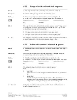
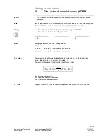
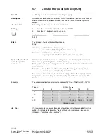
1. Press the line selection buttons to select line 22OEM.
2. Press the + / - buttons to set the required minimum limitation of the boiler return
temperature.
Setting range
Unit
Factory setting
8...95 °C
8
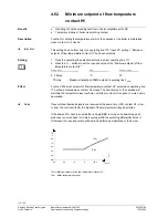
If the boiler return temperature drops below the minimum limit set here, the consumers’
heat c7onsumption will be restricted.
5.5
Calibration of actual output range of BMU 1-4
•
More accurate control through optimized signal transmission.
•
Calibration of the output signals delivered by the BMUs to match the actual values.
The output signals delivered by the BMUs can be calibrated to match the actual load.
This enhances the control performance.
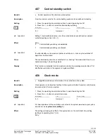
1.
Press the line selection buttons to select line 25OEM - 28OEM.
2.
Press the + / - buttons to adjust the calibration factors.
Setting range
Unit
Factory setting
-100...100 -
0
In that case:
- Operating line 25
=
BMU 1
- Operating line 26
=
BMU 2
- Operating line 27
=
BMU 3
- Operating line 28
=
BMU 4
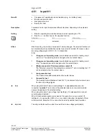
The output signal delivered by the respective BMU is corrected by the adjusted factor
and then used for controller-internal calculations.
In principle, operation without the adjusted calibration factor is possible, but to achieve
the greatest possible accuracy the adjustment should be made.
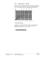
Calculation of the calibration factor for the respective BMU is made based on the
following formula:
P
%GS
K
%
=
P
%GS
100
P
Gs
P
N
1
100
Legend
K
%
Calibration
factor [%]
P
%GS
Output provided on the basic stage
[%]
P
GS
Output on the basic stage
[W]
P
N
Nominal
output
[W]
The value of P
%GS
is obtained by making a readout with the ACS69 service tool.
On the ACS69, the value is displayed on page “Heat source state“ under the name
“Actual capacity value BMU X“.
The values of P
GS
and P
N
are given on the type field of the BMUs.
Setting
Effect
Benefit
Description
Setting
Effect
Calculation
Note


