60/166
Siemens Building Technologies
Basic Documentation RVA47.320
CE1P2379E
HVAC Products
Description of the heating engineer settings
15.07.2002
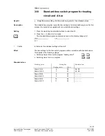
Actual values
•
Overview of the actual temperatures of the sensors used
•
Better reproducibility of the control sequences thanks to visualized temperatures
4.5
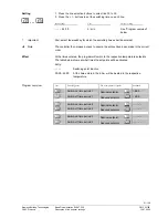
Actual boiler temperature values of BMUs
(TKx)
1.
Press the operating line selection buttons to select operating line 55.
2. Press the + / - buttons to interrogate the individual BMUs.
Display
Unit
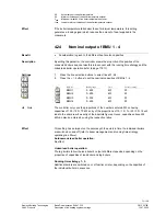
1...4 / 0...140
BMU number / °C
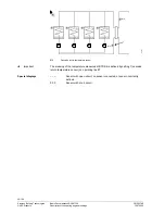
The lowest connected BMU number with the associated temperature will automatically
be displayed on this line. The temperatures of the other cascaded heating boilers can
be interrogated by pressing the + / - buttons. Non-existing BMUs will be skipped.
The cascade boilers displayed are only those connected to this controller. If there are
additional cascaded boilers, they will be displayed on the controllers to which they are
physically connected.
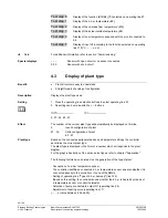
In place of the temperature, the following displays can appear next to the BMU number:
– – –
Sensor with an open-circuit or no sensor connected
0 0 0
Sensor with short-circuit
If the LCD displays – – – without giving an associated BMU number, there is no BMU
connected to the controller.
4.6
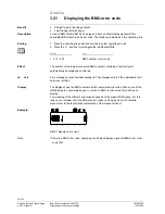
Actual value of cascade flow temperature
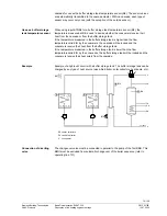
When using several cascaded heat sources, a cascade flow temperature sensor (B10)
must
be installed.
Also termed "Common flow temperature sensor”.
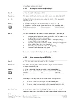
1. Press the operating line selection buttons to select operating line 56.
2. No setting can be made with the + / - buttons.
Display
Unit
0...140 °C
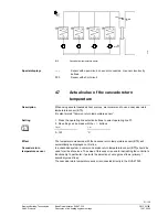
The temperature measured with the cascade flow temperature sensor (B10) will
automatically be displayed on this line.
In a cascaded system, a common cascade flow temperature sensor (B10) is used for
all heat sources.
The cascade temperature sensor (B10) is connected directly to the RVA47.320.
Benefit
Setting
Effect
Note
Special displays:
Note
Description
Setting
Effect
Cascade flow
temperature sensor


