


COMBIMASTER & MICROMASTER Integrated
REFERENCE MANUAL
©
Siemens plc. 1999
| G85139-H1731-U300-D2
29
Parameter
Function
Range
[Default]
Description / Notes
P056
Digital input debounce
time
0 – 2
[0]
Use a fast response time only when a ‘clean’ input signal is
used, e.g. from a PLC. Use a slow response time to allow
filtering of the signal if a noisy input (e.g. a switch) is used.
0
= 12.5 ms
1
= 7.5 ms
2
= 2.5 ms
P058 •
RUN command delay
(seconds)
0.0 -
650.0
[0.0]
Sets a time delay before the RUN command takes effect.
This parameter affects run commands from all sources
except the RUN button on the OPm2 (this starts the drive
immediately).
Value
Relay Function
Active
4
P061
Selection relay output
RL1
0 - 13
[6]
0
No function assigned (relay not
active)
Low
1
Inverter is running
High
2
Inverter Frequency 0.0 Hz
Low
3
Motor run right has been selected
High
4
External brake on (see parameters
P063/064)
1
Low
5
Inverter Frequency less than or
equal to minimum frequency
Low
6
Fault indication²
Low
7
Inverter frequency greater than or
equal to setpoint
High
8
Warning active³
Low
9
Output current greater than or equal
toP065
High
10
Motor current limit (warning)³
Low
11
Motor over temperature (warning)³
Low
12
Closed loop, motor LOW speed limit
High
13
Closed loop, motor HIGH speed limit High
1 External brake requires 24 V (max.) dc slave relay.
2 Inverter switches off (see parameter P930)
3 Inverter does not switch off (see parameter P931).
4 ‘Active low’ = relay OPEN. ‘Active high’ = relay CLOSED.
P062
Electro-mechanical
brake option control
0 - 4
[0]
This enables or disables the electro-mechanical brake
option.
Operation is the same as for P061 = 4, except that the
brake control voltage is supplied directly.
0
= Disabled
1 - 3
=
Do not use
4
= Enabled
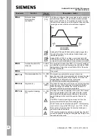
P063
External brake release
delay (seconds)
0 - 20.0
[1.0]
Only effective if the relay output is set to control an external
brake (P061 = 4) or the electro-mechanical brake option is
used (P062 = 4). In this case when the inverter is switched
on, it will run at the minimum frequency for the time set by this
parameter before releasing the brake control relay and
ramping up
(see illustration in P064)
.


