


COMBIMASTER & MICROMASTER Integrated
REFERENCE MANUAL
©
Siemens plc. 1999
| G85139-H1731-U300-D2
16
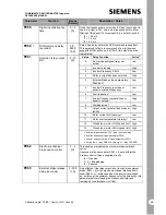
1.8mm max. screwdriver
Figure 6 Cable Connections with Drip Loop
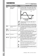
3 ~
M
C PU
A /D
SI
G R
ZK
W R
A/D
Analogue to Digital Converter
CPU
Microprocessor
GR
Rectifier
M
Motor
RS485 Serial Interface
SI
Mains Fuse
WR
Inverter
ZK
DC Link Capacitor
2
3
4
5
6
3
1
2
PE
Nom in al:
1/3 AC 208-240V
3 AC 380 - 500 V
L1, L2, L3
PE
U, V, W
1
P10+ (10 m A ) m a x.)
0V
PE
4
-
+
24 V
O R
O R
V :0-10 V
2-10 V
I
: 0-20m A
4-20m A
A IN +
A IN -
D IN 1
D IN 2
PE
+5V
N(-)
PL700 C S A
PL800 C S B
SK 200
0V
P(+)
11
12
8
9
Power supply for PI
feedback transducer
or other load
~
3 ~
RLB
RLC
RS485
Relay
Connections
Connections for
Serial Link or O Pm 2
7
D IN 3
+15V
10
PI-
PI+
Figure 7 Block Diagram
Figure 5 Connecting Control Wires to PL800


