


COMBIMASTER & MICROMASTER Integrated
REFERENCE MANUAL
©
Siemens plc. 1999
| G85139-H1731-U300-D2
18
2
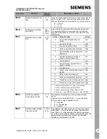
Using a combination of the internal
potentiometer and a run/stop switch:
a
Connect a run/stop switch between
DIN1 (pin 5) and P10+ (pin 1) on
PL700 (see Fig. 4) if forward
rotation is required. If reverse
rotation is required instead, connect
the switch to DIN2 (pin 6) instead of
DIN1 (pin 5).
IMPORTANT:
Remove the link, if fitted,
between pins 5 and 1 before the run/stop
switch is fitted.
b
Apply mains power. The green and
yellow LEDs will illuminate to show that
power is applied.
c
Set the external run/stop switch to ON.
d
Turn potentiometer R314 clockwise to
set the required motor speed.
e
Stop the motor by setting the external
on/off switch to OFF. When the switch is
set to ON again, it will run at the speed
previously set using the potentiometer.
5.3 Operation – External Analogue Control
1
Connect a 4.7 k
Ω
potentiometer to the
control terminals as shown in Fig.4 or
apply a 0 - 10 V signal between pin 2
(0V) and pin 3 (AIN+). In both cases,
position jumper JP304 to connect 0V to
AIN-.
2
Ensure that a link is fitted between pin 5
(DIN1) and pin 1 (P10+).
3
Check that voltage input is selected by
ensuring that the jumper is fitted to
JP301.
4
Refit the cover, tighten the cover
screws to the correct torque and then
apply mains power to the inverter.
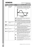
5
Turn the external potentiometer (or
adjust the analogue control voltage)
until the desired frequency is achieved.
The unit will not switch on until a
minimum of 2 V has been applied.
The frequency set by the
external voltage is added to
the frequency set by the
internal potentiometer. Refer to
Parameter P331 , Section 6.
As with Basic Operation, a run/stop switch
can be used to start and stop the motor, or
the direction of rotation can be changed by
connecting the link to DIN2 instead of DIN1.
5.4 Operation – Digital Control
This method of operation requires either a
Clear Text Display (OPm2) or a serial link
connection. The use of the Clear Text
Display module is described in the Options
section of this document. For a basic start-
up configuration using digital control,
proceed as follows:
1
Remove the link that connects control
terminal 5 to terminal 1 (if one has been
fitted).
2
Connect control terminal 5 to terminal 1
via a simple on/off switch. This sets up
the inverter for clockwise rotation
(default). If counter-clockwise operation
is required, connect a switch between
control terminals 6 and 1.
3
Connect the OPm2 or serial link to
SK200. Refit the cover, tighten the
cover screws to the correct torque and
then apply mains power to the inverter.
4
Set parameter P006 to 0 to specify
digital setpoint(see Section 6).
5
Set parameter P005 to the desired
frequency setpoint.
6
Set the external on/off switch to ON or
press the ON button on the OPm2 (set
P007 = 001 to use the OPm2). The
inverter will now run at the frequency
set by P005.


