


COMBIMASTER & MICROMASTER Integrated
REFERENCE MANUAL
©
Siemens plc. 1999
| G85139-H1731-U300-D2
23
Parameter
Function
Range
[Default]
Description / Notes
P005
••••
Digital frequency
setpoint (Hz)
0 – fmax**
[50.00]
Sets the frequency that the inverter will run at when
operated in digital mode. Only effective if P006 set to ‘0’.
Actual limit: CM: 120 Hz. MMI: 120Hz
-- -- -- -- -- -- -- -- -- -- -- -- -- -- -- -- -- -- -- -- -- -- -- -- -- -- -- --
SW Version : 3.00 onwards:
OPM display will be 650.00. Actual limit: CM: 90 – 140 Hz
(power rating dependent). MMI: 400Hz.
P006
Frequency setpoint
source selection
0 - 2
[1]
Sets the control mode of the inverter.
0
= Digital. The inverter runs at the frequency set in
P005.
If P007 is set to zero, the frequency may be adjusted by
setting any two of digital inputs P051 - P053 to values of
11 and 12.
1
= Analogue. The frequency is set via an analogue
input signal or the internal potentiometer.
2
= Fixed frequency or motor potentiometer.
one binary input (P051 - P053) = 6, 17 or 18.
If P006 = 1 and the inverter is set up for remote control
operation, the analogue inputs remain active (added to the
serial setpoint).
Motor potentiometer setpoints via digital inputs are stored
when P011 = 1.
P007
Keypad control
0 – 1
[0]
0
= The RUN, REVERSE and JOG buttons are
disabled. Control is via digital inputs (see
parameters P051 - P053).
∆
and
∇
may still be used
to control frequency provided that P124 = 1 and a
digital input has not been selected to perform this
function.
1
= OPm2 buttons are enabled (can be individually
disabled depending on the setting of parameters
P121 - P124). The digital inputs for RUN, JOG and
∆
/
∇
are disabled. If P121 – P123 are disabled,
digital inputs for RUN, JOG and REVERSE are
enabled.
P009
••••
Parameter protection
setting
0 - 3
[0]
Determines which parameters can be adjusted:
0
= Only parameters from P001 to P009 can be
read/set.
1
= Parameters from P001 to P009 can be set and all
other parameters can only be read.
2
= All parameters can be read/set but P009
automatically resets to 0 when power is removed.
3
= All parameters can be read/set.
P011
Frequency setpoint
memory
0 - 1
[0]
0
= Disabled.
1
= Enabled. The setpoint alterations made with the
∆
/
∇
buttons or digital inputs are stored even when
power has been removed from the inverter.
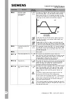
P012
••••
Minimum motor
frequency (Hz)
0 - 400.00
[0.00]
Sets the minimum motor frequency (must be less than the
value of P013).
P013
••••
Maximum motor
frequency (Hz)
0 – fmax**
[50.00]
Sets the maximum motor frequency.


