Siemens MAMMOMAT Novation DR Installation Manual Download Page 65

Image Quality

9 - 5

Siemens AG


SPB7-250.815.02

Page 5 of 20

MAMMOMAT 

Novation

DR

Medical Solutions

Rev. 02

09.04

CS SD 24

System


2.

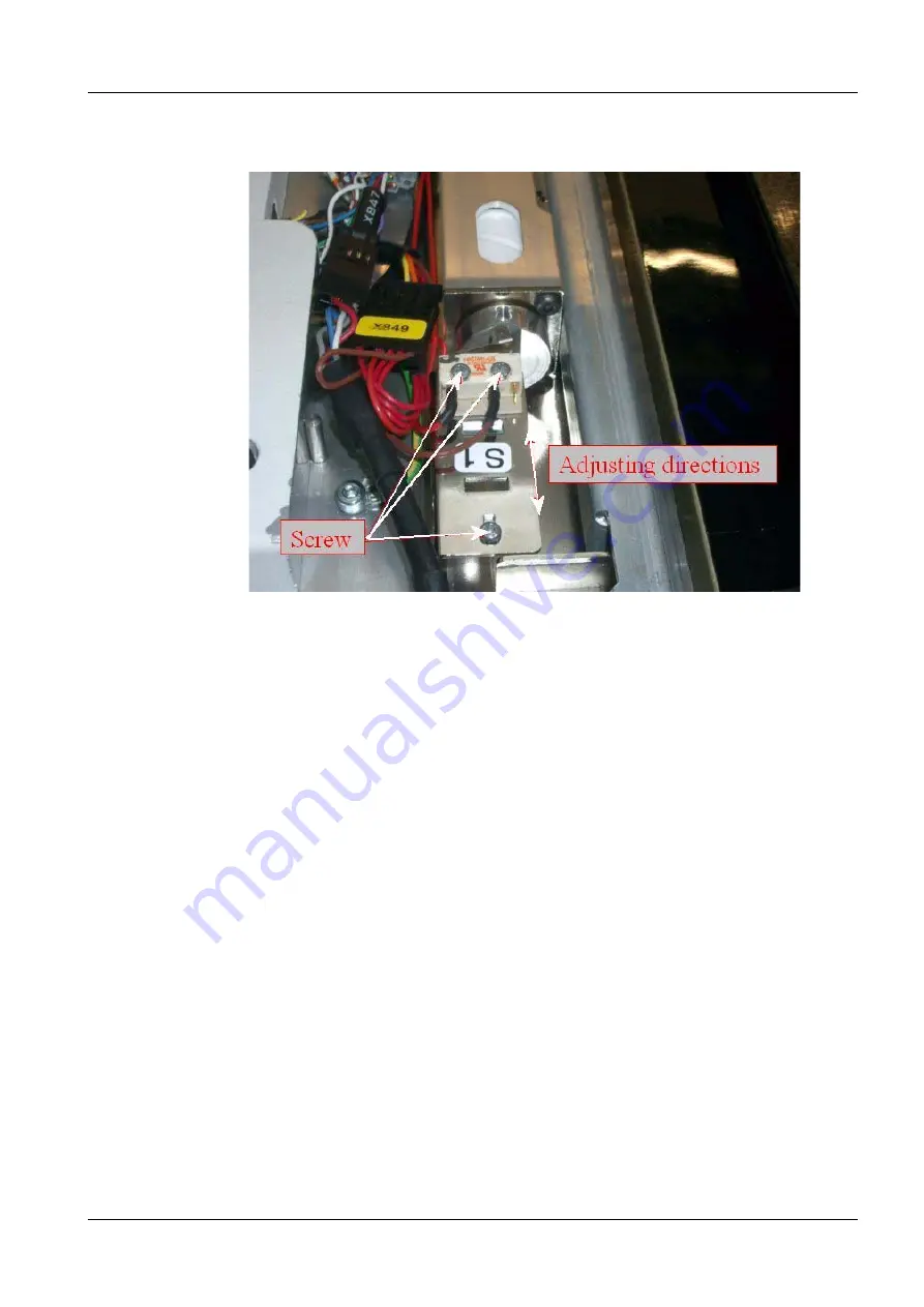
Loosen the three screws. Now it's possible to adjust the grid switch (S1) alongside 
the grid (see Fig. 4).

Fig. 4

Adjust grid switch S1

Summary of Contents for MAMMOMAT Novation DR

Page 1: ...mens AG 2004 The reproduction transmission or use of this document or its contents is not permitted without express written authority Offenders will be liable for damages All rights including rights created by patent grant or registration of a utility model _or_ design _are_ reserved SP System with WH AWS Startup ...

Page 2: ...current revision levels Disclaimer The installation and service of equipment described herein is to be performed by qualified personnel who are employed by Siemens or one of its affiliates or who are otherwise authorized by Siemens or one of its affiliates to provide such services Assemblers and other persons who are not employed by or otherwise directly affiliated with or authorized by Siemens or...

Page 3: ... 3 Service Software 2 3 Delay times between two exposures 2 4 3 _______Power up the MAMMOMAT Stand _________________________________ 3 1 Radiation protection door switch optional 3 1 External exposure lamp optional 3 1 Mains voltage 3 2 Electrical power to mains input 3 2 Connections 3 3 Measuring the line resistance 3 4 Checking the supply voltages 3 4 Checking the microprocessors LED s 3 5 Start...

Page 4: ... 6 1 Checks with a large focus and without AEC 6 3 Checks with a small focus and without AEC 6 4 Checks with a large focus and with AEC 6 5 7 ______ Collimator Adjustment __________________________________________7 1 Automatic collimator 7 1 Collimator reference axis 7 1 Collimator check 7 2 Collimator beam calibration 7 2 Collimator field light calibration 7 4 Collimator Wing Difference Calibrati...

Page 5: ... resistance 10 3 Warning label on control panel 10 4 Quality Certificate 10 4 11 ______Startup Protocol ______________________________________________ 11 1 Site Data 11 1 11 1 Auxiliary Materials used 11 1 Installation and Startup steps performed 11 2 Startup Settings 11 4 Tube high voltage current and mAs values 11 4 Collimator beam calibration 11 6 Collimator field light calibration 11 6 AEC Dos...

Page 6: ...OMAT NovationDR SPB7 250 815 02 Page 6 of 6 Siemens AG System Rev 02 09 04 CS SD 24 Medical Solutions Troubleshooting PC connection 12 6 13 _____ Changes to previous version ____________________________________13 1 Page ...

Page 7: ... Stand with the pivoted object table arm fixed and the integrated generator radiation shield with the integrated control console detector and syngo Acquisition Workstation Depending on the installation configuration some points may be omitted Fig 1 Configuration basic unit MAMMOMAT NovationDR tube assembly with filter disc Mo 0 03 Rh 0 025 Rh 0 050 Molybdenum tungsten anode X ray Integrated Genera...

Page 8: ... CS Intranet CS For Service Common Services Service Laptop for CSEs for details no Power line impedance meter 84 28 104 no Power ground wire tester 44 15 899 no Luminance meter for monitor calibra tion e g Mavo Monitor or Wellhöfer LXplus 05 146 167 97 02 432 no Luminance meter measures the light intensity from the X ray field e g SMfit Mammo 88 81 281 no Dose meter e g Solidose 88 81 323 no Ion c...

Page 9: ...00 alloy 4x4 cm 88 81 273 no Mammography line pair phantom 2 10 lp mm 88 81 299 no Collimator mounted plexi 4 cm yes Compression plate simulator yes 4 2 cm plexi Size of the detector 74 47 720 no Ethernet cable no Serial PC cable RS232 Array BRICK 66 55 745 yes Serial PC cable RS232 Stand 99 00 440 no Cassette Film 24x30 cm no Centering cross 96 60 051 no Tab 2 Phantoms and auxiliaries Item Remark...

Page 10: ...MAMMOMAT NovationDR SPB7 250 815 02 Page 4 of 4 Siemens AG System Rev 02 09 04 CS SD 24 Medical Solutions 1 4 Prerequisites This page intentionally left blank ...

Page 11: ...AMMOMAT NovationDR is recommended to be performed whenever a new MAMMOMAT NovationDR system has been installed and whenever changes that might affect performance have been made to an existing system The acceptance test of MAMMOMAT NovationDR involves performance of all QC proce dures in this Quality Control Manual SPB7 250 623 02 ensuring that a basic mini mum image quality criteria is met before ...

Page 12: ...will still be present at the generator line connection see wiring diagram A life threatening hazard of electric shock exists After shut down of the system there may still be 380 V DC present on the intermediate circuit A life threatening hazard of electric shock exists The PC boards contain electrostatic highly sensitive components If disregarded the components could be damaged Use ESD equipment g...

Page 13: ...ious service software packages Acquisition Workstation The Acquisition Workstation service software is web based and can be started from the Options application menu BRICK The BRICK service software can be accessed via the Acquisition Workstation Fig 1 Protective strips for the metal curtain The existing ground conductor in the mains cable must under no circumstances be disconnected when operating...

Page 14: ...ionDR Software manual SPB7 250 816 02 Delay times between two exposures 2 The delay times listed below must be followed to prevent the tube from overheating When the generator is switched off with the service PC con nected wait approximately 5 seconds before switching it on again The LED s H3 and H4 have to be off Exposure mAs value Delay time between two exposures seconds max 100 min 15 max 200 m...

Page 15: ... and connect the door switch instead If a radiation protections door switch is not used a jumper see Fig 1 on the master board 750 at connector X754 Pin 1 2 has to be inserted External exposure lamp optional 3 This should only be performed if the customer requires it The connection on the Master board works as a shutter The signal from the Master board is only active during exposure thus the expos...

Page 16: ...0 Hz Electrical power to mains input 3 Mains voltage 1 phase 208 230 240 and 277 V 10 or 2 phase 208 230 240 277 and 400 V 10 Mains Frequency 50 or 60 Hz Maximum load 10kVA momentary and 0 8 kVA long time load Fuse 25 A external 208 400 V Do not use power from the MAMMOMAT stand Before the power for the MAMMOMAT is turned on make sure that the cable plugs left and right of the system for the Magni...

Page 17: ...e incoming mains cable Power system Type of connection Power voltage Power connections Single phase Phase to neutral 208 V 277 V Connect to 3 and 4 see 1 Fig 3 Two phase Phase to phase 208 V 400 V phase to phase Note Max 277 V phase to neutral ground allowed Connect to 3 and 4 see 1 Fig 3 Use two phases of three in a normal power distribution sys tem The left over wires neutral and the third phase...

Page 18: ...ne resistance must not exceed the following values Checking the supply voltages 3 The correct supply voltages 5 V 15 V and 28 V have already been tested in the fac tory Only a visual check of the function is therefore needed 1 Switch the system ON 2 Check that the following LED indicators top to bottom on the mains input converter generator are on Nominal Input Voltage VAC Line Resistance Rimax c ...

Page 19: ...MMOMAT system completely 3 Turn the external power switch ON 4 Check that the power up of the Generator and the BRICK are performed properly 5 Start the MAMMOMAT system by pressing the power button ON on the control console 6 Check that the MAMMOMAT system is powering up correctly 7 Check that the BRICK and the Acquisition Workstation communication is working properly LED s V2 and V3 need to be gr...

Page 20: ...cribed in the document Startup WH AWS SPB7 250 815 02 Arranging the swivel arm 3 1 Remove the protective strips from the metal curtain 2 Run the lifting carriage upwards 3 Attach the protective strips back onto the metal curtain 4 Rotate the swivel arm system to 0 degrees by pressing one of the switches for clockwise rotation on the supporting arm 5 System and mains OFF Never rotate the swivel arm...

Page 21: ...System Detector installation 4 Unpacking of the detector 4 1 Open the cardboard boxes and remove the top packing insert 1 Remove all of the other packing material covering the inner box in which the detector is located Fig 1 Opening the cardboard box Fig 2 Opening the box Do not cut the lifting band NOTE ...

Page 22: ...SD 24 Medical Solutions 4 2 Detector installation 1 Lift the inner box from the large box by pulling up on the lifting band 1 Slide the lifting band from the inner box 2 Lift out the detector and carefully remove from wrapper Fig 3 Lift out the inner box Fig 4 Remove packing material ...

Page 23: ...tects the imaging area The imaging electronics under the front cover are extremely sensitive The actual image area starts at the front edge and is approximately 25 mm inside the other three edges Any dust or fingerprints in this area may affect final image quality Temperature extremes may cause permanent damage Fig 5 Check temperature logger When the LED lights green transportation was OK and the ...

Page 24: ...he bolts are tightened 5 Insert the detector cable underneath the grid holder and tighten the grid holder screws again 4 Fig 6 6 Connect the detector cable 3 Fig 6 to the cable coming out of the wing 2 Fig 6 7 Mount the cover over the detector cable with 2 screws Make sure that no cables are squeezed Fig 6 Detector installation To be sure that the detector is correctly mounted and that it is locat...

Page 25: ...k into the rail 2 Insert the left and right grid holder into the grid slider 2 Fig 7 3 Line up the grid to the front of the table the front switch has to be engaged Screw the grid 3 Fig 7 to the grid holder 4 Fig 7 The marking has to be on top text must be readable 4 Connect the cables 5 Fig 7 for the magnification table according to the labels on both sides Fig 7 Grid installation Make sure that ...

Page 26: ...fication table S3 must switch 2 mm 1 mm tolerance before the magnification table reaches the end position Mounting the covers 4 1 Mount the bottom wing cover with 6 screws 2 Mount the top wing cover with 4 screws 3 Slide the detector fibre cover carefully over the detector and fasten it with 6 screws at the bottom of the cover Fig 8 Micro switch installation The magnification table is optional Whe...

Page 27: ...unt the cable duct covers Swivel arm covers 5 Before installing the side covers the cables have to be connected 1 Connect cables X807 1 Fig 1 to control button circuit boards D807 2 Fig 1 2 Connect ground wires 3 Fig 1 to patient handles 4 Fig 1 Side covers 5 Screws in different sizes are included in the delivery Fig 1 Connecting the cables Fig 2 Covers and sign 2 2 4 4 1 1 5 5 2 3 4 5 1 6 ...

Page 28: ...e front cover upwards and let it snap in position over the side covers 4 Fasten the front cover to the side covers with two short screws 5 Fig 2 Do not forget to fit the sign 3 Fig 2 when mounting the side cov ers Use the two longer screws Make sure that the longer screws are not used at the back of the covers at the upper location 6 Fig 2 since this may damage the board underneath the cover Risk ...

Page 29: ...the rear cover 4 Fig 3 to the stand and fasten it with screws 5 Fig 3 and contact washers 6 Fig 3 The edges of the metal curtain of the stand are very sharp They may cause severe injury Remove the protective strips carefully when the covers are to be mounted Store the strips in the holders provided on both sides of the curtain When mounting the stand covers make sure that the screws at the top of ...

Page 30: ...rip 7 Fig 3 to the front and side covers and fasten with screws 1 Fig 3 eight on either side 6 Press on the outer plastic strip 8 Fig 3 Stand cap 1 Place the Stand cap on the top of the MAMMOMAT stand 2 Fig 4 Face shield 5 1 Slide the face shield 1 onto the holder for external diaphragms Checking the swivel arm system Fig 4 Stand cap Fig 5 Face shield 2 1 ...

Page 31: ... arm system will be blocked 2 System ON detector table installed and projection angle set to minimum with presetting knob 1 Fig 6 3 Check the rotary motion of the swivel arm system by pressing buttons 2 Fig 6 one by one The rotation of the swivel arm system will stop when the button is released or when the end position is reached 135 degrees clockwise and 180 degrees counterclockwise The projectio...

Page 32: ...ched and at 0 degrees Vertical adjustment 5 1 Press the buttons for upward and downward movement 3 Fig 6 of the swivel arm system Fig 7 Display at the lower part of the stand All eight rotary motion buttons four on either side 2 Fig 6 must be checked After the button has been released the swivel arm system shall remain in the position set Remove the protective strips before performing the vertical...

Page 33: ...utton is released Emergency stop 5 1 Press the emergency stop button 4 Fig 6 The button will latch and all motorized movements of the equipment will be blocked Er 813 shall appear To reset the emergency stop button turn it clockwise All eight vertical adjustment buttons four on either side 3 Fig 6 must be checked The switching off in upper and lower end posi tion is effected by switches S881 and S...

Page 34: ...s 5 8 Mechanical Checks Checking the field light time 5 1 Switch on the field light by pressing the switch 1 Fig 8 or by pressing the compression foot switch 1 Fig 9 The field light shall go out automatically after a preset period of time normally 20 s Fig 8 Field lightswitch Fig 9 Foot switch 1 MAM00133 1 ...

Page 35: ...eous Illumination time 3 Type in the illumination time and save with F2 Checking the compression device 5 1 Attach the compression plate 1 Fig 10 if you have not already done so 2 Check that the compression plate cannot be removed without pressing the compression plate release button 2 Fig 10 3 Check the function of the knobs for manual compression decompression 3 Fig 10 4 Place a piece of soft ma...

Page 36: ...g the compression plate in the opposite direction by hand The upward movement of the compression plate shall now stop safety switch 7 Set the compression to 7 kg by using the presetting knob 5 Fig 10 The preset compression force is shown on the display at the lower part of the stand 1 Fig 12 8 Press the foot switch for motorized compression to move the compression plate downwards while simultaneou...

Page 37: ...5 15 kg depending on the material 4 Fig 10 used Adapting OPCOMP If the factory set OPCOMP is not to the customer s satisfaction an adjustment can be car ried out with the tautness factors in the Optimized compression dr table see Service Instructions Software SPB7 250 816 02 A lower tautness value will increase the compression force and vice versa Increase decrease the tautness factor by e g 10 th...

Page 38: ...2 09 04 CS SD 24 Medical Solutions 5 12 Mechanical Checks Checking the exposure blocking 5 Check that the exposure release is blocked during the following conditions No patient is registered No compression plate is mounted The wing is not in position Fig 13 Swivel arm system ...

Page 39: ... that the tungsten anode is enabled Switch the system ON Set the cassette loaded switch to OFF with the Service Program In the Main menu choose Configuration Miscellaneous Cassette loaded check Measurement method 6 The mAs value must be calculated as the product of the tube current and exposure time The tube current and the exposure time can be obtained from the oscillograms The diagram may have g...

Page 40: ...diagram examples Fig 2 Fig 3 30 kV 1 V T 1 T 5 kV 30 kV 1 V T 1 T 5 kV 130 mA 1 V T 1 T 40 mA 166 mA 1 V T 1 T 40 mA 160 ms 20 ms T 128 ms 20 ms T Fig 4 Fig 5 35 kV 1 V T 1 T 5 kV 35 kV 1 V T 1 T 5 kV 112 mA 1 V T 1 T 40 mA 132 mA 1 V T 1 T 40 mA 0 9 s 0 2 s T 0 72 s 0 2 s T 30kV 20mAs Mo Mo 30kV 20mAs W Rh 35kV 100mAs Mo Mo 35kV 100mAs W Rh ...

Page 41: ...ith a lead apron Test performance 1 Adjust the exposure value on the control console according to the table above 2 Start an exposure 3 Check and measure the kV value and the tube current characteristic on the oscilloscope The accuracy of the kV is 5 for tube current 10 and for the mAs product 10 4 Record the measured kV and mAs value in the Startup Protocol on Page 11 1 5 Change the setting and c...

Page 42: ... performance 1 Adjust the exposure value on the control console according to the table above 2 Start an exposure 3 Check and measure the kV value and the tube current characteristic on the oscilloscope The accuracy of the kV is 5 for tube current 10 and for the mAs product 10 4 Record the measured kV and mAs value in the Startup Protocol page 11 1 5 Change the setting and continue with the next me...

Page 43: ... the exposure value on the control console according to the table above 2 Start an exposure 3 Check and measure the kV value and the tube current characteristic on the oscilloscope The accuracy of the kV is 5 for tube current 10 and for the mAs product 10 4 Record the measured kV and mAs value in the Startup Protocol page 11 1 5 Change the setting and continue with the next measurement until you h...

Page 44: ...MAMMOMAT NovationDR SPB7 250 815 02 Page 6 of 6 Siemens AG System Rev 02 09 04 CS SD 24 Medical Solutions 6 6 X ray tube checks This page intentionally left blank ...

Page 45: ... This field will correspond to the radiation field during the exposure When the exposure preparation is started the col limator lamellae are adjusted to the currently selected anode focus i e to get the radiation field Exposure will not be allowed as long as collimation is not ready or a not valid object table and compression paddle combination has been selected Maximum time to change the size of ...

Page 46: ...cting 25 kV and 50 mAs on the control console 5 Start an exposure 6 View the image with a magnification of 4 7 Slide the magnification glass along the image edges of the image and check if white lines are visible Collimator beam calibration 7 Collimator calibration is carried out for each focus including the field light focus 1 Connect the compression plate simulator and the collimator mounted ple...

Page 47: ...alues by 5 numbers 5 Select a focus anode combination 6 Make sure a patient is registered and start an exposure 7 Use a magnification of 4 in the application software and go to the edges of the detector White areas should be visible at all edges of the image This shows you that the X ray does not cover the entire detector and shows where the beam really ends 8 Measure the white line thickness at e...

Page 48: ...Configuration Collimator Calibration of light field 2 Position the X ray cross in the center of the detector 3 Make sure that a patient is registered 4 Mount the Collimator Mounted Phantom 5 Mount the compression simulator 6 Deselect H and D on the control console by selecting 25 kV and 50 mAs on the control console 7 Start an exposure 8 Compare the image with the reading of the X ray cross on the...

Page 49: ...alibration and Exit the Service Software 12 Record the measured values in the Startup Protocol on Page 11 1 Collimator Wing Difference Calibration 7 The collimator wing difference calibration has to be set to 0 1 Start the service software on the Service PC and select Configuration Collimator Calibration of wing differance 2 Save the calibration and Exit the Service Software Fig 4 Collimator wing ...

Page 50: ...MAMMOMAT NovationDR SPB7 250 815 02 Page 6 of 6 Siemens AG System Rev 02 09 04 CS SD 24 Medical Solutions 7 6 Collimator Adjustment This page intentionally left blank ...

Page 51: ... of HVL Half Value Layer and Dose Exchange factors can be performed to improve the accuracy of displayed dose val ues These measurements should be performed by the hospital s medical physicist and are described in the document Radiographic Handbook Dose Calculation System SPB7 230 206 01 The measuring procedure is quite complicated and should only be performed by a physicist familiar with similar ...

Page 52: ...ons 8 2 Checking dose settings Label 8 If the Dose Calculation System is enabled affix a mAs mGy label over the mAs text on the control and display panel The label is found in register 3 of the Technical Manual binder Auto Lim Program Mo Mo Mo Rh Rh W AEC mAs mGy WARNING kV Fig 2 affix the new label here ...

Page 53: ... SPB7 250 620 01 for the correct OPDOSE val ues Changes can be made with the service PC program Configuration Miscellaneous Auto limits 1 Mount a 18x24 cm compression plate 2 Select a thickness of calibration plexi part no 65 61 240 that is within the thickness interval of the program to be tested 3 Select AUTO on the control panel 4 Place the calibration plexi on the object table and compress to ...

Page 54: ...l console have to be checked As a default from the factory the following BRICK AEC Configuration values are set for further details see the Software Brick V manual SPB7 250 816 04 H 80 70 45 D 100 80 60 Checking the H D dose settings for Mo Mo 8 Proceed as follows 1 Mount the Collimator Mounted Plexi phantom and the compression plate simulator 2 Register or create a patient and submit with Exam Fi...

Page 55: ...posure 7 Measure the following values and add them to the table at step 4 Remember you can always add or remove images to the Procedure by using the right mouse click AEC kV Anode Filter Dose Value Pixel Value H 28 kV Mo Mo D 28 kV Mo Mo Tab 1 Checking H D dose settings for Mo Mo If parts of the meter probe covers the AEC sensor one will get a higher dose Thus make sure that the probe is not cover...

Page 56: ...click on the Viewing tabcard load the image with the Patient Browser and select Tools Rect angle Draw an area of approximately 1 sq cm and measure the pixel mean value You have to measure approximately 2 cm above the chest wall at the center of the detector Criteria The expected pixel mean values are H 250 350 D 300 400 8 If the H D dose settings have to be adjusted proceed with Chapter 8 Adjust t...

Page 57: ...measured in step 2 Display the image with the syngo Image Viewer To do so click on the Viewing tabcard load the image with the Patient Browser and select Tools Rect angle Draw an area of approximately 1 sq cm and measure the pixel mean value Add the result to the table The Mo Rh and W Rh pixel values must be as close as possible to the Mo Mo pixel values see table at step 2 The deviation must not ...

Page 58: ...own menu above the values To change the values permanently enter the correct values and select save then use load to load them before you start another exposure Calculation of the new Mo Mo dose scaling value NewScalingValue OldScalingValue DoseValueNominal DoseValueMeasured DoseValueNominal for H 130 µGy DoseValueNominal for D 190 µGy Calculation of the new Mo Rh W Rh dose scaling values NewScali...

Page 59: ...0 45 and enter the new values separated by a comma e g 80 70 45 in the Low Dose Scal ing Value field and click Change Low Dose Scaling to save it D value go to Modify high dose scaling The default values are 100 80 60 and enter the new values separated by a comma e g 100 80 60 in the High Dose Scal ing Value field and click Change High Dose Scaling to save it 6 Proceed from where you have been ref...

Page 60: ...MAMMOMAT NovationDR SPB7 250 815 02 Page 10 of 10 Siemens AG System Rev 02 09 04 CS SD 24 Medical Solutions 8 10 Checking dose settings This page intentionally left blank ...

Page 61: ...ble in one or more images the grade of grid lines must be measured The criteria for the mean pixel value difference of the visible grid lines is less then 1 Eliminating Grid lines on Page 9 4 Pre Conditions The system is up and running The operator is logged in to the system The compression plate simulator is mounted on the MAMMOMAT Checking visibility of grid lines 9 1 Register or create a patien...

Page 62: ...magnification Image Magnify by 2 0 and look for grid lines over the plexi phantom area 7 Note the result visible grid lines in Tab 1 choose the next image in the list and start over with step 5 until all images are evaluated Test 1 Protocol Remember you can always add or remove images to the Procedure by using the right mouse click Exposure Exp Mode mAs PMMA mm Tube Angle Visible grid lines yes no...

Page 63: ...elect Tools Rectangle Draw an area of approximately 1 sq cm and measure the pixel mean value You have to measure approximately 2 cm above the chest wall at the center of the detector 2 Activate magnification Image Magnify by 2 0 3 Select Tools Rectangle and draw a rectangle on the background according to Fig 3 X The rectangle should be approximately 5 cm long 4 Make a new rectangle on a grid line ...

Page 64: ...d line problems Adjust the grid switch Adjust the wheel that is mounted on the grid motor Adjust the grid location Adjust the grid switch The switch S1 see Fig 4 on the detector table disables the high voltage when the grid is in the turning point The switch must be correctly adjusted otherwise the high voltage will be active when the grid is standing still To minimize the risk that the high volta...

Page 65: ...AG SPB7 250 815 02 Page 5 of 20 MAMMOMAT NovationDR Medical Solutions Rev 02 09 04 CS SD 24 System 2 Loosen the three screws Now it s possible to adjust the grid switch S1 alongside the grid see Fig 4 Fig 4 Adjust grid switch S1 ...

Page 66: ...ivates or deactivates 4 Fasten the three screws 5 Move the grid to the other end position and check that the grid switch activates deactivates on either edge of the slit see Fig 6 and Fig 5 Adjust the wheel that is mounted on the grid motor A wheel is mounted on the left side of the grid motor M1 on the wheel there is a slits which activates the grid switch S1 1 Move the grid to the left end posit...

Page 67: ...d position 4 Check if the slits are horizontal to the detector table see Fig 7 5 If the slits isn t horizontal loosen the screw on the wheel and adjust it so the slits is horizontal in both end positions Adjust the grid location 1 Open the carbon detector cover 2 Make sure the grid in mounted in parallel to the detector and lined up to the front of the table The front switch has to be engaged Fig ...

Page 68: ...ers and analog to digital conversion to generate a digital signal While the charge amplifiers are matched small differences in their performance can result in differences in the X ray densities detected for the same amount of X ray Performing calibration allows the system to detect these small differences along with other variables that can affect the digital signal output The system can then appl...

Page 69: ...AG SPB7 250 815 02 Page 9 of 20 MAMMOMAT NovationDR Medical Solutions Rev 02 09 04 CS SD 24 System 2 Select Acquisition System 3 As a result you will get the following screen Fig 8 Service Home Page Fig 9 Acquisition System Menu ...

Page 70: ...y 4 Select Gain Calibration The data from the last Calibration will be displayed After pressing the Start button the last calibration data will no longer be valid The temperature field in this picture shows a value of 3045 due to a bug in the software The actual temperature value is 30 45 WARNING Fig 10 Calibration Enter NOTE ...

Page 71: ...11 of 20 MAMMOMAT NovationDR Medical Solutions Rev 02 09 04 CS SD 24 System 5 Press the Start button to start the calibration 6 Create or register the patient Calibration and submit with Exam Fig 11 Calibration Start Fig 12 Calibration Patient register ...

Page 72: ...late simulator 11 Double click on the first Image of the 8 at the Procedure Calibration Procedure 12 Start an exposure Wait until the image is loaded into the viewer The following lines are displayed in the message bar Image acquisition is in progress Saving processed Image Loading Image 13 Check the image quality of the image No objects or artifacts shall be visible in the image If you Accept the...

Page 73: ...rocedure and continue with step 12 14 Wait approximately 10 seconds for the image to be calculated observe the status bar and then double click on the next image in the Procedure Calibration Procedure and proceed with step 12 until you have a total of 8 images 15 Click Done to exit the Calibration 16 Close the examination You would Reject an image if it exhibits any edge cut off due to collimation...

Page 74: ...ly and so should be ignored when the image is acquired This is similar to a bad spot map for a computer s hard disk A new pixel map should be created when an excessive amount of pixel dropout is occur ring repeatedly on images displayed in the Image Preview window To create a new pixel map 1 Log into local service Options Service Local Service 2 Select Acquisition System Make sure that no patient ...

Page 75: ...250 815 02 Page 15 of 20 MAMMOMAT NovationDR Medical Solutions Rev 02 09 04 CS SD 24 System 3 As a result you will get the following screen 4 Click the Bad pixel mapping link Fig 15 Acquisition System Menu Fig 16 Bad Pixel Mapping Enter ...

Page 76: ...04 CS SD 24 Medical Solutions 9 16 Image Quality 5 Press the Start button to begin with the Bad Pixel Mapping As a result the following screen is displayed If you want to end the Bad Pixel Mapping operation at this point click the Cancel button Fig 17 Bad Pixel Mapping start NOTE ...

Page 77: ...7 Siemens AG SPB7 250 815 02 Page 17 of 20 MAMMOMAT NovationDR Medical Solutions Rev 02 09 04 CS SD 24 System 6 Register the pre defined patient Calibration and submit with Exam Fig 18 Bad Pixel Mapping Patient register ...

Page 78: ...tom 10 Mount the compression plate simulator 11 Double click on the first Image of the 8 at the Procedure Calibration Procedure 12 Start an exposure Wait until the image is loaded into the viewer The following lines are displayed in the message bar Image acquisition is in progress Saving processed Image Loading Image 13 Click the Accept or Reject button If you want to end the Bad Pixel Mapping ope...

Page 79: ...e the Bad Pixel Mapping menu is displays Correct the problem and return to step 12 14 Click Done to exit the Bad Pixel Mapping 15 Close the examination If you want to end the Bad Pixel Mapping operation at this point click the Cancel button You would Reject an image if it exhibits any edge cut off due to collimation or misalignment or if there are any artifacts from debris or obstructions Fig 20 B...

Page 80: ...Raw and QC Processed procedures To do the QC manual the QC Raw and the QC Processed procedures are necessary 1 Check if both procedures exist in the WH AWS application software Options Configuration Proc Hand If they don t exist you have to create them as follows 2 Add the QC Raw procedure with the following parameters in the Proc Hand application Projection Views Add 10 R CCs Examination Operatin...

Page 81: ...NTER Test performance 1 Start the Service Software for the MAMMOMAT Stand on the Service PC 2 In the Mainmenu select Configuration Clock 3 Press F2 With F2 the date and time set in the service PC are taken over by the MAMMOMAT stand BRICK 10 Setting the date and time on the BRICK 1 Go into the service software and select Utilities Escape to OS and enter the following command in the command field s...

Page 82: ...cedures 3 To see the current date and time setting on the BRICK use the following command brick date To set the date and time on the BRICK use the following command brick date mmddHHMMyy mm month dd day HH hours MM minutes yy year The following example sets the system to 3 10 p m on November 21 2004 brick date 1121031004 ...

Page 83: ...n menu 1 Select Backup Copy installation area to floppy All 2 Leave the program with F10 when the backup is ready Remove the measuring instruments 10 1 Turn OFF the MAMMOMAT 2 Remove the service PC 3 Remove connected measuring instruments Checking the protective grounding resistance 10 Using the protective ground wire tester measure the resistance between the protective ground terminal in the stan...

Page 84: ...cks immediately Quality Certificate 10 The SP Q Quality Certificate has to be filled out and signed The form can be found in the chapter 9 Certificates of the technical documentation binder Appendix of 66 46 900 QZE 01S 00 It has to be sent to the address stated on the certificate only when Installation or Start up problems occurred Place a copy of the SP Q Quality Certificate in the technical doc...

Page 85: ...ation team Project manager Installation start Installation end Item Model Calibration date Serial number Oscilloscope 50MHz with memory Digital multimeter including a mAs meter Power line impedance meter Power ground wire tester Luminance meter for monitor calibration Luminance meter measures the light intensity from the X ray field Dose meter Ion chamber Densitometer A non invasive digital kV met...

Page 86: ...v 02 09 04 CS SD 24 Medical Solutions 11 2 Startup Protocol Installation and Startup steps performed 11 Work performed yes no Installation The MAMMOMAT NovationDR was installed completely All Covers are mounted The temperature logger was sent to DirectRay Cooperation DRC ...

Page 87: ...formed Collimator checks performed Dose Settings checked Acquisition Workstation configurations performed Configured DICOM services Image Quality tests performed Acceptance tests performed Ground wire tested Line resistance tested Backup for Acquisition Workstation and MAMMOMAT created SP Q Quality Certificate filled out and sent when problems occurred with either the installation or startup Work ...

Page 88: ...___ kV ______ mAs 30 kV 20 mAs W Rh _____V x 5 kV _____V x _____s _____s _____s x 40 mA ______ kV ______ mAs 35 kV 100 mAs Mo Mo _____V x 5 kV _____V x _____s _____s _____s x 40 mA ______ kV ______ mAs 35 kV 100 mAs W Rh _____V x 5 kV _____V x _____s _____s _____s x 40 mA ______ kV ______ mAs 25 kV 100 mAs Mo Mo _____V x 5 kV _____V x _____s _____s _____s x 40 mA ______ kV ______ mAs 25 kV 100 mAs...

Page 89: ...____s _____s _____s x 40 mA ______ kV ______ mAs 25 kV Mo Mo _____V x 5 kV _____V x _____s _____s _____s x 40 mA ______ kV ______ mAs Display ______ mAs 25 kV W Rh _____V x 5 kV _____V x _____s _____s _____s x 40 mA ______ kV ______ mAs Display ______ mAs kV mAs Anode filter Measured values Result kV must be 5 mAs must be 10 Tab 2 Tube high voltage current and mAs values ...

Page 90: ...esults from the chapter Collimator field light calibration on Page 7 4 AEC Dose Settings 11 Results from the chapter Checking the AEC dose settings on Page 8 4 Focus and Anode XL XR YC YS Small focus molly Large focus molly Small focus tungsten Large focus tungsten Tab 3 Collimator beam calibration XL XR YC YS Light field Tab 4 Collimator field light calibration AEC kV Anode Filter Dose value Pixe...

Page 91: ...Page 8 3 Checking Grid Lines 11 Results from the chapter Checking Grid Lines on Page 9 1 Program button Thickness kV Anode filter combination AEC 1 2 3 4 Tab 6 OPDOSE Settings Expo sure Exp Mode mAs PMMA mm Tube Angle visible grid lines yes no X Y Mean pixel value differ ence 1 mAs 32 30 0o 2 mAs 56 40 0o 3 mAs 200 60 0o 4 AEC H 40 0o 5 AEC H 40 60o 6 AEC H 40 60o Tab 7 Measuring Grid Lines ...

Page 92: ... End Date start of work end of work time E Bringing in the entire system in hours per day M Installation of the entire system in hours per day V Cabling of the system in hours per day R Travelling time in hours per day KA No order related working time in hours per day Work performed Work performed in the time Employees number Number of employees who were employed in the period Total Mh Man hours n...

Page 93: ..._____________________________________________________________ __________________________________________________________________________ __________________________________________________________________________ __________________________________________________________________________ __________________________________________________________________________ ______________________________________...

Page 94: ...MAMMOMAT NovationDR SPB7 250 815 02 Page 10 of 10 Siemens AG System Rev 02 09 04 CS SD 24 Medical Solutions 11 10 Startup Protocol This page intentionally left blank ...

Page 95: ...ticular problems A key step in analysis is to isolate the artifact to the component that is producing it First similar appearing artifacts can come from anywhere in the overall image chain Second the tendency to assume that the artifact is coming from the least known component must be avoided For example artifacts that appear to be coming from the detector may actu ally be coming from the output d...

Page 96: ...tector on Page 9 8 Perform detector calibration procedure refer to Calibration of detector on Page 9 8 Perform the bad pixel correction refer to Creation of new pixel map on Page 9 14 Line Parallel to the Long Axis Line ends at seam or line partially defective gate lines Detector not calibrated properly Line needs to be mapped out Perform detector calibration procedure refer to Calibration of dete...

Page 97: ...c interference with or along cable Check pins and Detector connection to PXCM Identify and isolate sources of inter ference examine the cable pathway Fine Linear Pattern Parallel to Long Axis in One or More 256 Blocks usually more pronounced on an edge Electromagnetic noise interfering with Detector Read Out Shield Motors power sources and so on located in proximity to the detector Other Artifacts...

Page 98: ...hat at this point the space key must be pressed xx yy zz Data can be entered in place of x y z e g day s date Curved brackets indicate that out of several terms listed one be low the other one must be selected Important remarks are indicated with this box When the password is entered only these characters are shown Menu Selection When several menus programs files etc are presented for selec tion t...

Page 99: ...edure has to be done only once Configuration of computer BIOS 12 1 Enter the BIOS setup usually done by pressing e g F2 during the boot sequence of the BIOS 2 Find the configuration of the IrDA Infrared device port and disable it 3 Find the configuration of a built in modem and make sure it is configured as COM3 4 Find the configuration of COM1 and make sure it uses the interrupt IRQ 4 and the mem...

Page 100: ... the technician for example NN and then press ENTER 5 The program asks for the password Password please Type the password and then press ENTER The display window shows Main menu 6 Select the program part to be used with keys and or then press ENTER The program part selected is shown with a background If necessary additional subroutines can be similarly selected here 7 Make the necessary entries in...

Page 101: ...0 815 02 Page 7 of 8 MAMMOMAT NovationDR Medical Solutions Rev 02 09 04 CS SD 24 System 8 Choose the tab Port Settings 9 Press the button Advanced 10 Uncheck the check box Use FIFO Buffers 11 Exit the dialog by pressing the OK button ...

Page 102: ...MAMMOMAT NovationDR SPB7 250 815 02 Page 8 of 8 Siemens AG System Rev 02 09 04 CS SD 24 Medical Solutions 12 8 Appendix This page intentionally left blank ...

Page 103: ...e meter and ion chamber 4 3 The detector package has to be disposed of locally Corrected the temperature logger return process 8 3 Deleted the OPDOSE values and referenced to the Instructions of use Added a description of OPDOSE Made modifications in regards to the opdima changes 10 1 Added time adjustment for the BRICK 11 all Corrected the startup protocol regarding the opdima changes Added a tab...

Page 104: ...MAMMOMAT NovationDR SPB7 250 815 02 Page 2 of 2 Siemens AG System Rev 02 09 04 CS SD 24 Medical Solutions 13 2 Changes to previous version This page intentionally left blank ...

Reviews: