


09.02
Connection
Siemens AG 6SE7087-6AK85-1AA0
3-3
Rectifier/Regenerating Unit Operating instructions
WARNING
The operating coils of contactors and relays that are connected to the same supply
network as the unit or that are located in close proximity of the unit must be connected to
overvoltage limiters, e.g. RC circuits.
An RCCB (residual-current-operated circuit-breaker) must not be used to protect the
rectifier/regenerating unit (DIN VDE 0160).
Voltage is only permitted to be applied to the unit when SIMOVERT Master Drives are
connected. Operation without a connected DC link capacitor is not permitted!
If the DC link terminals are connected incorrectly or short-circuited, the SIMOVERT Master
Drives inverter will be destroyed!
To reduce mains pollution, limit harmonics and reduce current ripple, the total system
inductance for the supply and feedback connection (incl. commutating reactor and, where
applicable, autotransformer must result in a total relative short-circuit voltage uk between
4% and 10%.
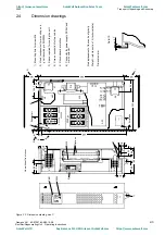
Connect the fan power supply to X19.
The fan continues to run for about four minutes or until a certain cooling element
temperature threshold is undershot (provided its power supply is connected) after the unit
has been switched off, following fault messages, on canceling the enable signal and after
isolating the system supply connection.
Despite switching the voltage off at the power terminals, a voltage may still exist on
terminal X19 due to the external fan supply.
NOTES
The supply voltages applied to the rectifier and regenerating power terminals (U1/L1, V1/L2, W1/L3 and
1U2/1T1, 1V2/1T2, 1W2/1T3) must have an identical phase angle and identical frequency.
Recommendation: The inductive components of the impedance drop uk of the (auto) transformer should lie
between 1.5 and 3% (see Table 3.4).
Commutating reactor: Selection of the reactors for 4 % uk should be based on the rated current in
regenerative mode on the line side (see Technical Data). In weak or low-power systems, the uk of
the commutating reactor must be decreased in order not to exceed the upper limit for the total uk of
10%. A further measure in the case of extremely high uk values for the supply network can be
implemented by connecting the primary side of the autotransformer to the supply network directly
(before the commutating reactors), to ensure that the total uk value in the regenerating direction will
not be too high.
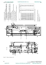
Rectification
Regeneration
DC link
Mains
Arrangement for high-power system
Arrangement for low-power system
Rectification
Regeneration
DC link
Mains
For the selection of the commutating reactors, see Table 3.6 and Catalog DA93.1.
With an extremely high total uk value in the regenerative direction, it may be necessary due to the
increased thyristor current commutating time, to reduce the inverter step limit (parameter P776). This
may mean it is necessary to reduce Ud.
Output reactors in the DC circuit are not permitted (even with the parallel connection of power sections or
in 12-pulse mode), because the DC link voltage is measured at the unit output terminals.
https://www.aotewell.com
AoteWell Automation Sales Team
AoteWell LTD
Buy Siemens PLC HMI Drives at AoteWell.com
https://www.aotewell.com


