


Start-Up
09.02
4-62
Siemens AG 6SE7087-6AK85-1AA0
Rectifier/Regenerating Unit Operating Instructions
Functionality according to layer 2
The user data from the user software (as COBs on byte level) must be transferred directly to layer 2 (see also
the examples of PZD and PKW data exchange given further down).
Functionality according to layer 7 (CANopen)
CANopen is not supported by the SIMOVERT 6SE70 rectifier unit
.
CAN protocol
Device Net
Device
profile
Application
Communication
profile
CIA
DS 301
Layer 7
Application layer
CIA CAL
DS 201 .. 205, 207
CAL
Device net
specification includes:
- Device profile
– Communication
profile
– Application layer
Layer 3-6
Layer 2
Data link layer
ISO-DIS 11898
Physical layer,
electrical
Communication
Layer 1
Physical layer,
mechanical
CIA DS 102-1
Device Net ODVA
4.5.3.1
Description of CBC with CAN Layer 2
User data are exchanged between the CAN master and the CAN boards on the drives, i.e. the slaves. User
data are categorized as either process data (control and status information, setpoints and actual values) or data
which relate to parameters.
Process data (
PZD
s) are time-critical and therefore processed faster by the drive (every 3.3 ms at system
frequency of 50 Hz) than the non-time-critical
PKW data
(parameter identifier value), which is processed by the
drive every 20 ms.
All settings required to operate the communication board are made in drive parameters.
Process data (PZD) are categorized as either data received by the drive (control words and setpoints:
PZD
Receive
) or data transmitted by the drive (status words and actual values:
PZD Send
). A maximum of 16 PZDs
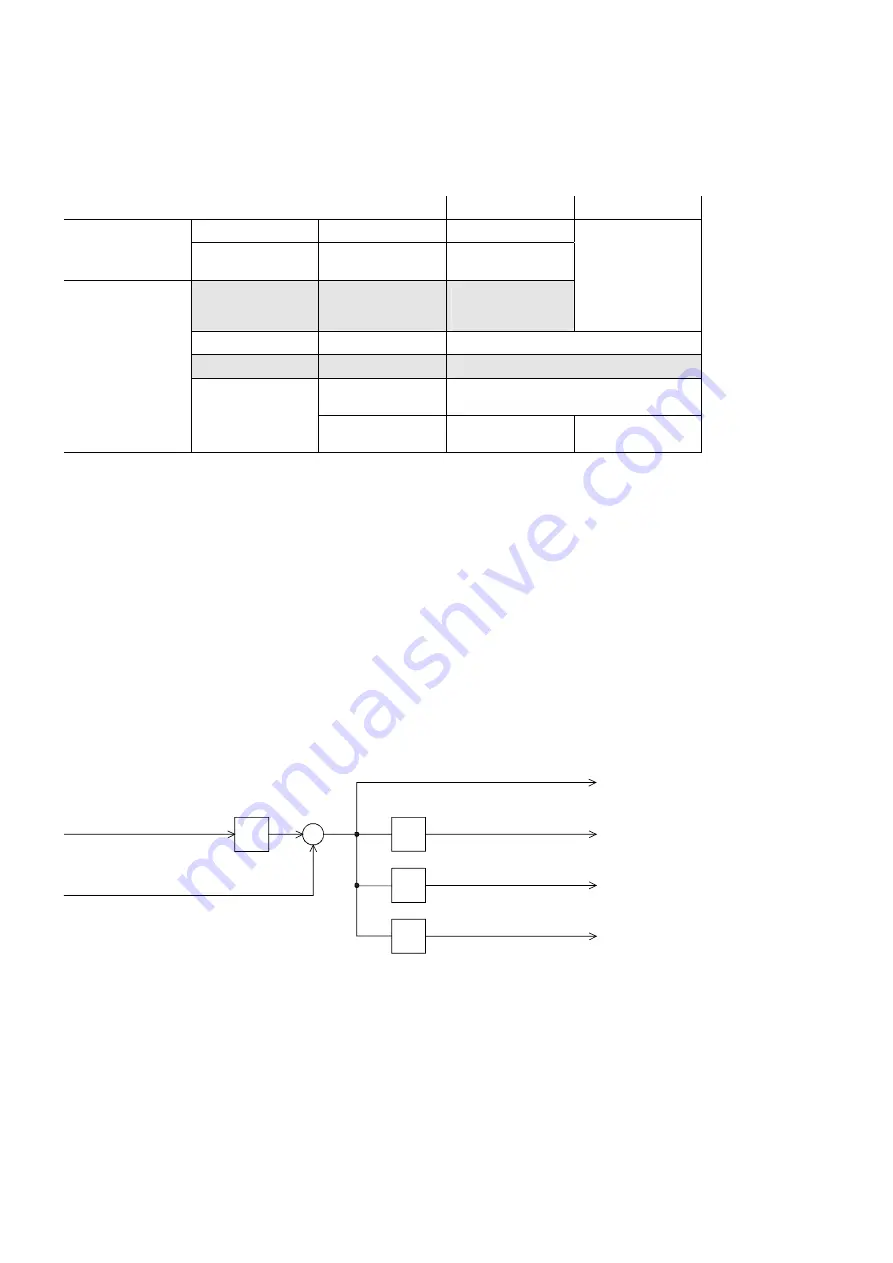
can be transferred in either direction; these are divided into COBs with 4 data words each by the
communication board. In other words, 4 COBs are required to transfer 4 PZD words, with each COB requiring
its own separate identifier. Identifiers are assigned in the CB parameters as shown in the following diagram:
x4
+
+1
+2
+3
Node address
of drive (P918)
Basic identifier for parameterizing
PZD Receive (U712)
PZD Receive 1 (setpoints 1 to 4)
PZD Receive 2 (setpoints 5 to 8)
PZD Receive 3 (setpoints 9 to 12)
PZD Receive 4 (setpoints 13 to 16)
Example of PZD Receive:
P918 = 1
This settings assigns identifier 100 to the first 4 receive PZDs,
P697 = 96
identifier 101 to the second 4 receive PZDs, etc.
https://www.aotewell.com
AoteWell Automation Sales Team
AoteWell LTD
Buy Siemens PLC HMI Drives at AoteWell.com
https://www.aotewell.com


