Approach
1.
Mount kit 1a or 1b on the mounting surface.
2.
Mount the safety laser scanner on mounting kit 1a or 1b.
NOTE
When mounting the device, observe the dimensional drawings.
Further topics
•
"Dimensional drawings", page 135
5.2.3
Mounting using mounting kits 2 and 3
Overview
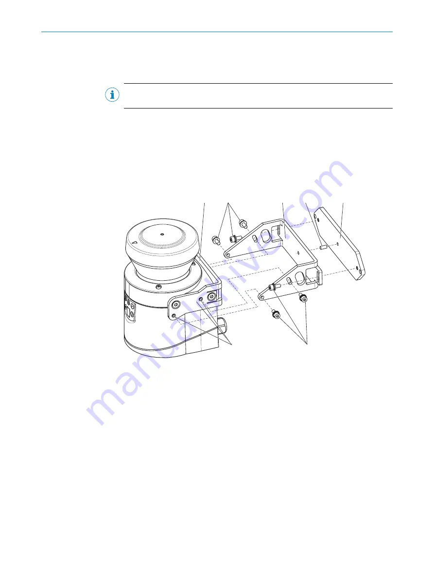
You can use mounting kits 2 and 3 (only in conjunction with mounting kit 1a or 1b) to
align the device in 2 planes. The maximum adjustment angle is ± 11° in both planes.
1
2
3
5
6
4
2
Figure 51: Mounting using mounting kit 2
1
Mounting kit 1a
2
Fixing screws
3
Mounting kit 2
4
Centring pin
5
Mounting kit 3
6
Threaded holes M4
Approach
1.
Mount kit 1a or 1b on the safety laser scanner.
2.
Mount kit 3 on the mounting surface.
3.
Insert the centering pin (4 mm) into the center hole of mounting kit 3.
4.
Fit the mounting kit 2 onto mounting kit 3 and mount using two M4×10 fixing
screws.
5.
Mount the safety laser scanner on mounting kit 2 using the threaded holes in
mounting kit 1a.
6.
Adjust the safety laser scanner along the longitudinal and transversal axis then
tighten the six fixing screws on the mounting kits.
5
MOUNTING
62
O P E R A T I N G I N S T R U C T I O N S | S300
8010948/ZA21/2020-06-18 | SICK
Subject to change without notice


